I’ve never used that service, but could be useful for some, any idea on cost?
I programmed my modules with 5v as well. IMO, there is a desired unintended outcome when flashing with 5v: when the programming is completed; the module should ALWAYS go into bypass mode (red led is illuminated indicating that the modules is sending the excess voltage (5v-4.2v = 0.8v) into the resistors.)
I had one module (hand soldered) that finished programming but did NOT go into bypass mode. I double checked my soldering and my quality was sub-par. I would have never caught this with the naked eye under a 2x magnifying glass. It was only when the module did NOT go into bypass that I realized there was a problem with the board not the software.
One piece of advice, I was programming and it takes about 3 minutes to complete a single board. I had to leave my chair and get rid of some beer, er I mean coffee. It took a little longer than I anticipated. When I returned, the programming was complete and the module was in bypass mode. I had the module on a piece of plastic and the heat from the board caused the plastic to melt…so please be careful when using 5v to flash the modules…and NEVER program with 5v if the module is connected to the 3.7v cells…I am not sure the end results but I bet it will not be good.
One more item to add to the discussion. During my recent (past 4 days) set up issues; I purchased a 16M d1-mini-pro. I thought I received defective 4M d1-mini (turns out it was operator error).
The d1-mini-Pro had no issues whatsoever. It sync’d to my router and started working immediately.
One question though, on all my modules; when I connect them for the first time (to single cells); the modules enter by pass mode for a complete cycle or two. The voltage is under 4.1v for each cell. Is this normal? After a cycle or two, the modules will exit by pass mode and function normally.
Hi,
I have a little problem with the boards.
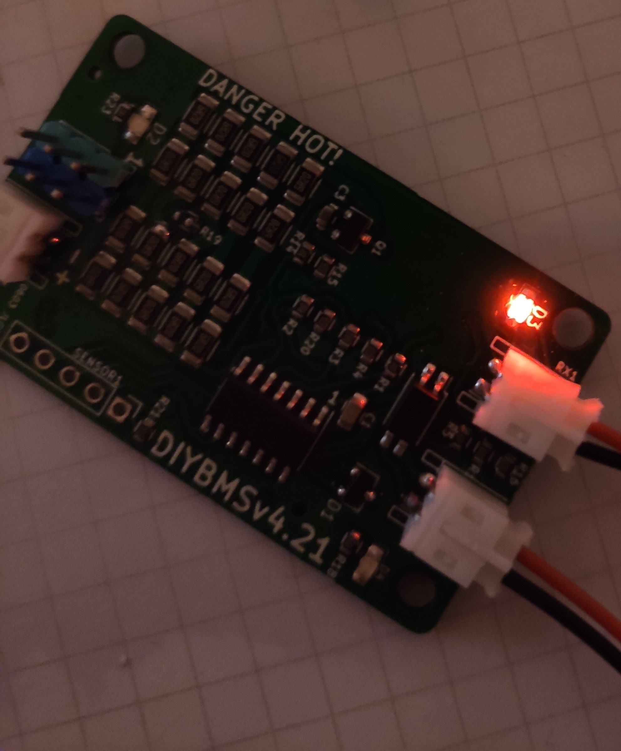
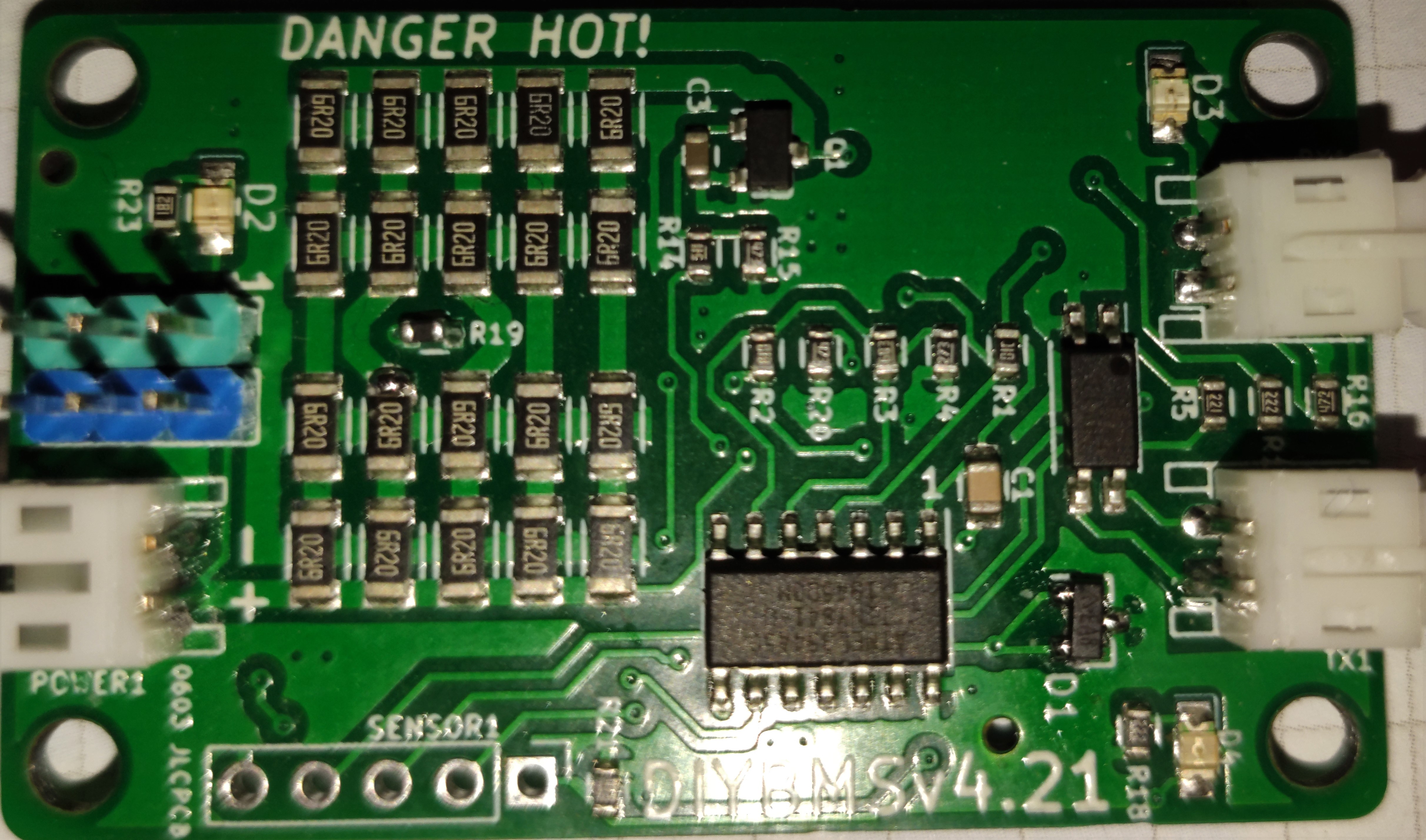
When I connect the battery to the board, D2 and D4 light up briefly. After a few seconds, D3 starts to flicker red and discharges the battery and the resistors become hot.
D1 is an (AZ432ANTR-E1) and R19 is an (NCP18WB473J03RB SMD). I soldered the two myself, the rest is from JLC. Are these the wrong components?
[Welcome, SId1. Your post was marked a suspicious by the system: “New user typed their first post suspiciously fast, suspected bot or spammer behavior.” - Moderator (RW)]
What firmware were you using for this module, the “releases” version or directly from PlatformIO.
The board shouldn’t get this hot. Is this a V4.21 module ?
That sounds like it’s working perfectly!
What voltage are the cells at?
I wouldn’t say that is normal, might be worth checking the bypass voltage is set as you expect. Click the “global settings” button in Modules to save a default.
Well i now have all the components and successfully flashed a few modules and a controller for a test setup.
I have the V4.21 boards assembled by JLPCB (except the attiny) Is there a specific branch i should flash to the 4.21 board? I flashed the cell modules in the ‘General’ branch and everything works except the resistors get extremely hot.
The resistor will get hot 65 to 70 degrees.
Thanks Stuart. Do i just flash the cell module with the general branch? i noticed in the fix swapped R1920 branch there is an option to build using attiny841_V421
Hi Stuart,
Yes it is v4.21. I did not measure the temperature but the plastic was probably PVC, which softening point is about 75C.
Yes use the master branch
Hi Stuart,
the error was the too high voltage. It was at 4.15 volts. In addition, I had no connection from the controller to the boards. I reloaded the program on the controller and then it worked. Thanks for your great project!

not yet.
Apparently its for USA “only” as they are programmed in the USA.
NOT at the branch offices!
Bummer.
if you want to use you need to fill in all kinds of paper for “export” pre-programmed chips.
I didn’t look at the papers needed to fill, as only transport time and costs make it not usable for me.
And i assume they like to get some money for the programming as well.
For people who live in the USA, or are willing to wait the extra time and spend the extra money, I’ve asked for price indication.
Not yet received!
Nice thought, but for the sake of a a minute or two per module to program them not a show stopper.
I’m just finishing off a YouTube video on how to order and program the relevant components.
2 Likes
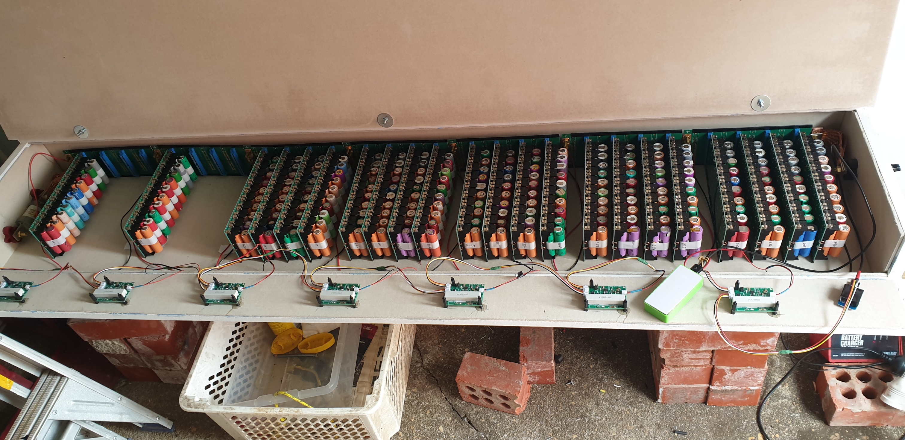
Nice , see you doubled up on the cells what sort of capacity/ runtime you getting and are you still using only 5 amp fuses?
Well i have to say many thanks to Stuart and the team here.
I had JLPCB make the PCB’s and install surface mount components (except for the attiny) I then hand soldered the attiny in place thanks to the help of some very useful YouTube videos. I flashed both the cells and the controller without a hitch once again following some helpful YouTube tutorials.
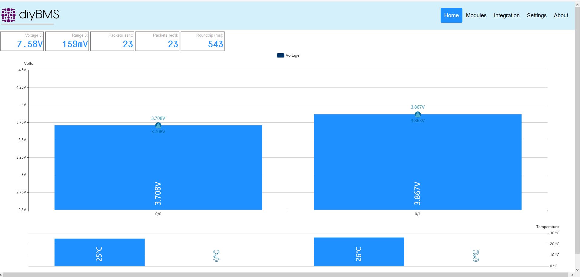
I now have the BMS running on a 3S4P test pack and it is behaving exactly as expected. The BMS integrated with influxdb with ease and I am now producing some nice graphs to compliment the diyBMS web interface.
Once again congratulations on a very successful project.
3 Likes
I saw that Adam Welch did a video on ordering boards from JLCPCB and getting them solder the SMD components. The video link is tucked away in a comment of his on the V2.41 module boards video. Strangely, it isn’t in the list of his other YouTube videos.
Since we all are DIY’ing big battery packs i was wondering where do you all get you’re cells from.
I personally use the 18650 cells from old bike batteries but running short on suppliers as a result of Belgian strict recycle regulations.
Any other ideas on this?
2 Likes