Connect the controller using a usb cable.
Open a serial terminal to the controller, reboot it and press space bar when it powers up.
You can then select a new WiFi hotspot
Connect the controller using a usb cable.
Open a serial terminal to the controller, reboot it and press space bar when it powers up.
You can then select a new WiFi hotspot
Hello all,
Not sure if this is the correct place to post this, so apologies if I’ve got it wrong!
I’m looking at using diyBMS with an 18S LiFePO4 setup, it’s 4P totalling to about 840Ah off the top of my head. It’s going onto a Victron setup with a Multiplus 10000VA inverter, smart solar MPPT and Cerbo GX.
My question is, should i use just 1 module/slave board for all the 4P cells, or divide them in two or four and have multiple module/slave boards, for the paralleled cells.
Secoundly, I assume diyBMS is happy integrating with victron Cerbo? And if so, should i add a separate contactor for the batteries or is this not necessary normally?
Thanks!
Why 18S? Typically people use 16S and that’s what the diybms all in one monitor board is for - monitoring 16 cells in 1 module.
Because the batteries are in modules of 6S that can’t easily be divided up as they’re welded tabs. I’ve only just arrived at this installation but I’m rather worried it’s all too high voltage for the victron systems. I suppose that would put an absorption voltage of about 65V. Is that too high for victron stuff, I’ve not worked with Victron before. It’s a 250/100 MPPT.
This is far from the only 18s Victron system out there. As long as your solar array yields higher voltage than the batteries, you’re all good.
The MPPT’s data sheet says that its “equalization voltage” is 64.8V by default in a 48V system, which is perfect when you have 18S of LiFePo4 (3.6V per cell).
Ok thanks, i’ll give it a go seeing as it’s what we have. Back to the original question, would it be recommended to run parallel module boards or just one per parallel bank?
Secondly on Victron integration, is diyBMS generally rather happy with this? Any need to run a contactor inline with the cells or not really
Thanks!
Hi, Everyone,
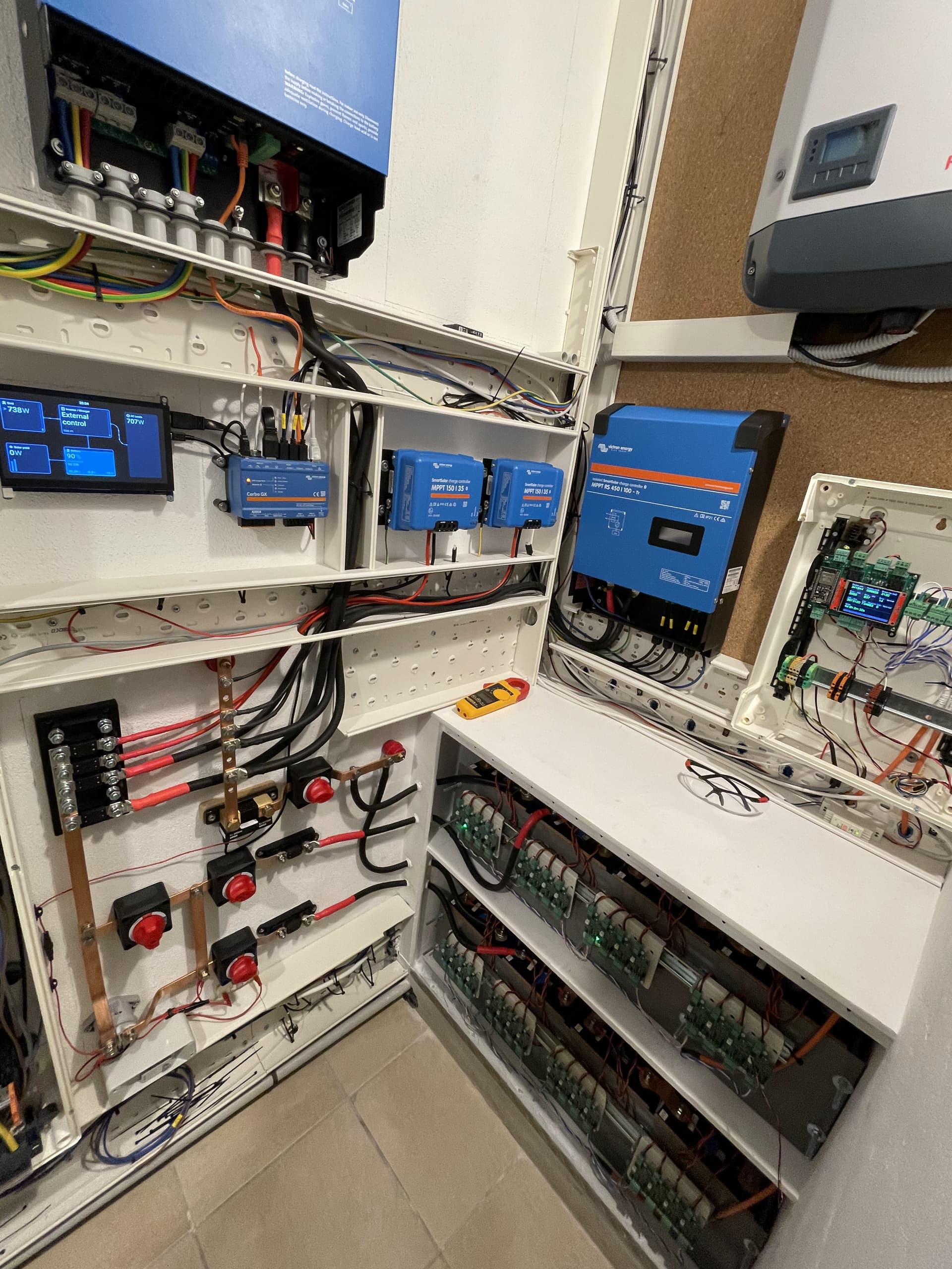
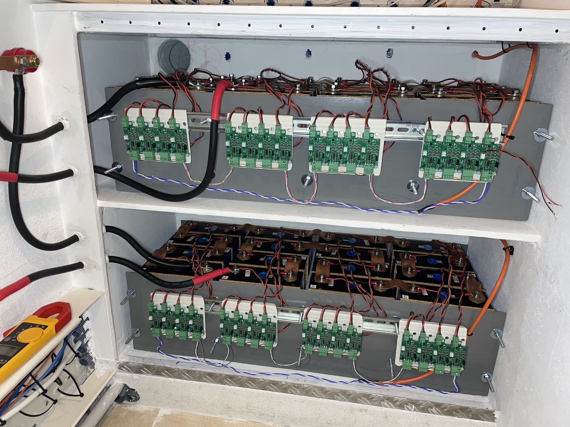
Thanks to all of you and Stuart especially, i realise the project of 32 cell of lifepo4 with the V4.5 modules. (I started to assemble the devices when the all in one was not available)
I’ve did few days only of testing and seems to work good.
I Connected the Victron cerboGX to the diyBMS controller via CAN.
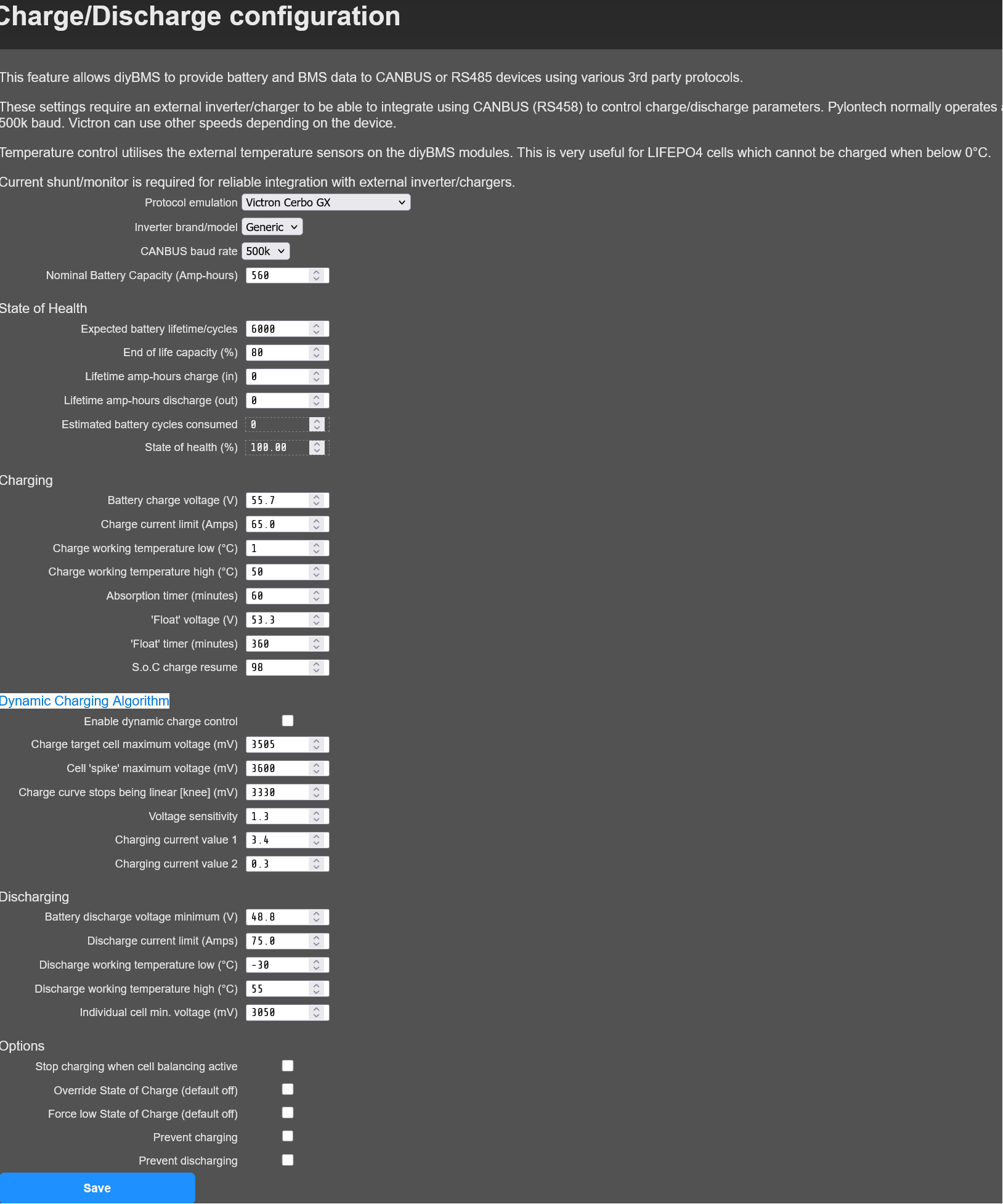
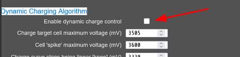
But i have problem with the “Dynamic Charging Algorithm”.
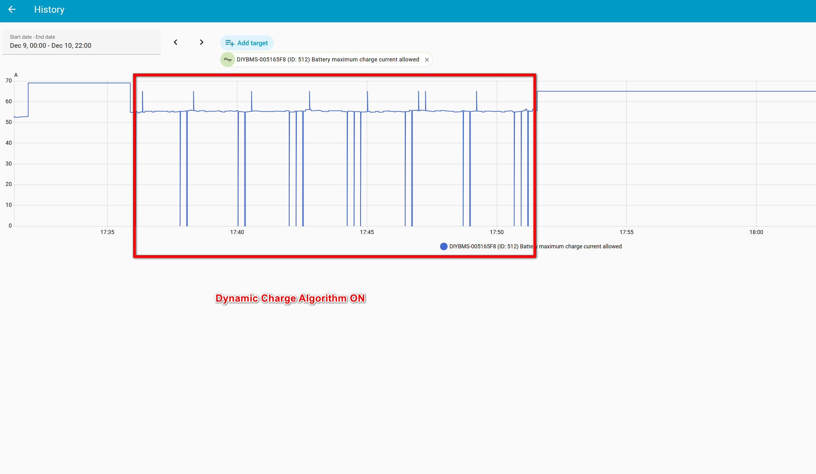
If activated, during charging the charging stop for some short, see the Victron Smart Shunt monitoring current attach.
Seems the BMS sometimes send the value 0 to the Maximum current allowed for 1seconds.
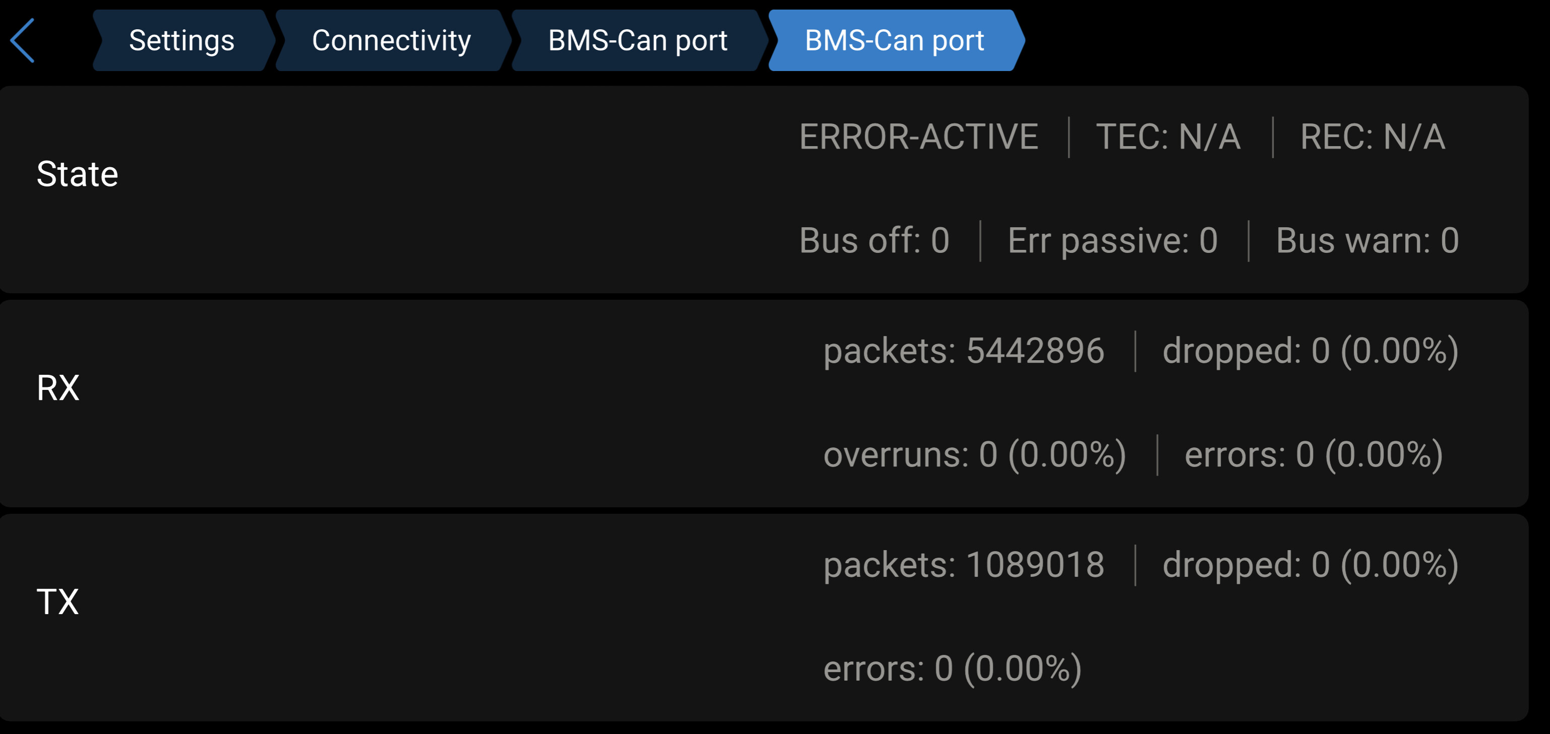
There is no CAN problem see attach.
There is no reset of the bms.
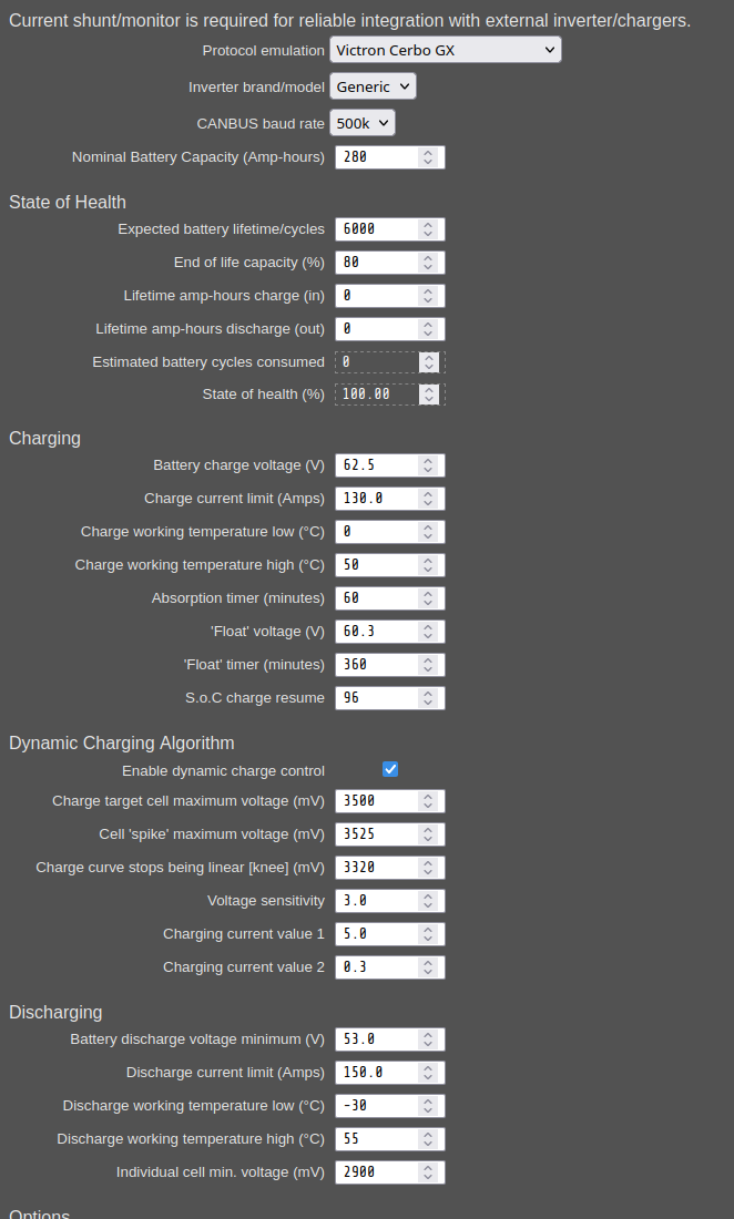
what about my parameters in diybms, are they ok ?
I don’t have diybms shunt, only Victron smart shunt.
Let me know what information i can give you more to help solve the problem ?
Thanks for help
Mickael
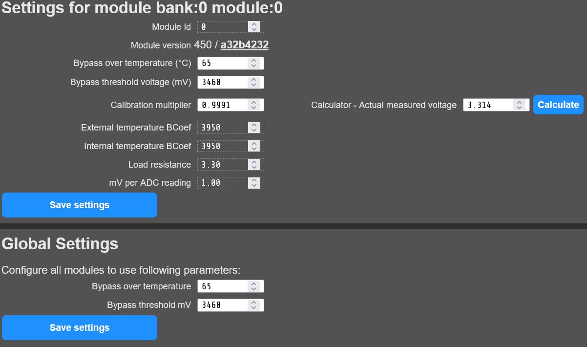
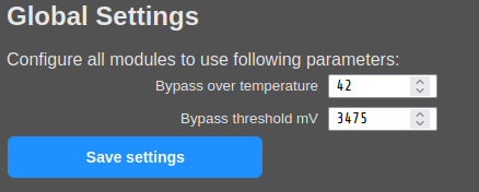
What did you enter as global settings for the modules?
I currently only have the Victron shunt and am not experiencing this behaviour.
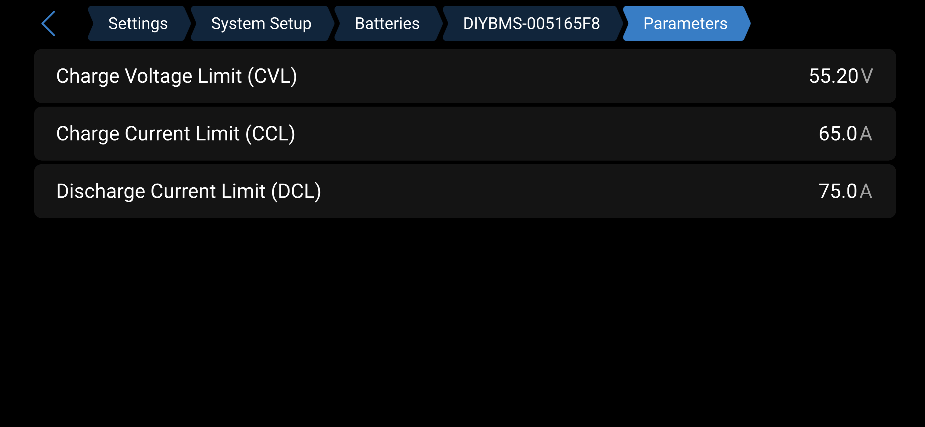
In the Victron VRM portal, you can also view the CVL and CCL values under “Advanced”. You could take a screenshot there.
Hi, Thanks for reply
Here is my settings for module 1 but all the same for other module except calibration that i did.
CVL and CCL work fine and are updated good.
But when i activate “dynamic charge algorithm” sometime CCL drop to 0 for 1second and the inverter instantly stop charging, and start again. We can hear a “clack” noise in the Multiplus at this moment
I connected the diybms to Home assistant via MQTT and can see the value CCL drop to 1sec.
This problem happends since the first start of the installation.
To find the source of the problem i was thinking :
Why during normal charging (battery voltage at about 3,3V ) diybms controller could send CCL = 0 to the cerbo ?
Also is it normal that the display of the tile “Charge mode” is always written “Standard” ?
Thanks
Best regards
Yes it is on purpose because i activate for testing only as i’m afraid my inverter will not like this if i leave for long time.
relay made noise when current drop so fast.
Thanks, i took my settings here from “stuart”
I’m not a programmer so i don’t know where to search but i did testing again and connected putty on serial port for logging but i didn’t understand what to look for.
I just noted problem happends around line 523784
and on line 577013, i uncheck “dynamic charging” and no more charging problem.
diybms log_2025-12-12.txt (91.8 KB)
I have seen reports of this with another inverter over can bus.
I added lots of logging to the controller code, but never found the root cause. From what I could see, the controller never sent the zero current setting.
I’m interested in your mqtt logging though, is that just logging from diybms? Perhaps we can use that to find the issue.
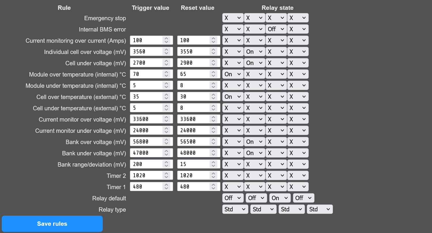
Do you have any rules that are triggering (temperature etc)?
Thanks,
On the diyBMS controller ESP side, i connected to serial usb port on diybms but i didn’t found the problem on the log diybms log_2025-12-12.txt
But maybe i don”t know what to search for.
On the Victron Cerbo GX side, connected MQTT to home assistant, i found this graph where we can see this current dropping.
What do you mean by “ From what I could see, the controller never sent the zero current setting “ ?
On my picture graph we can see “Battery Maximum Charge Current Allowed” dropping to 0 many times
If you saw this on the CAN bus it means this value come from the ESP.
Maybe a variable in the calculation that could end up to send overt the CAN bus “Battery Maximum Charge Current Allowed” = 0 sometimes ?
Let me know what loggin i can do, problem happends instantly as i check dynamic charge algorithm.
There is a check in the code which runs before any data is sent on the can is - it basically checks the BMS is in a safe position/configuration including the rules.
If this is fails it’s checks it will default to ‘stop’ charging - I’m wondering if this is what you are seeing, something isn’t happy!
Although you don’t use the rules with the relays, the logic in them is used for this check, so make sure they are configured with meaningful values.
i have an issue - after 1 and a half year of working perfect my ESP, LevelShifter and CAN-Tranciever burned suddenly - First i assumed overvoltage of 5V supply - but my dc/dc has good output voltage.
Now i have to replace this parts and after that i will check if there are other defects.
Are there any issues known on Controller v4.5?
No known/reported issues like you reported - could have been a surge on the 5V supply, any chance something touched the board/shorted out?
Hi @mktime
The code for the Victron integration is all here.. diyBMSv4ESP32/ESPController/src/victron_canbus.cpp at 210a268982c8ab72ccea4992d3abab10c4be162f · stuartpittaway/diyBMSv4ESP32 · GitHub
The code runs very frequently and starts with a default of zero max. charge current as an assumed safe position.
The code also runs several checks to see if the various rules and settings/cell voltages etc are all in a known safe range, and if so, the max. charge current is set in the CANBUS message (351).
The checks are in the code IsChargeAllowed and IsDischargeAllowed.
So, if you can use the latest code I’ve just deployed on GITHUB branch - please download the artifacts from here (you will need to login to github)… Update graph library · stuartpittaway/diyBMSv4ESP32@71eddfc · GitHub
Monitor the serial output of the controller, we are looking for errors along the lines of…
I (287463) diybms-rules: Set warning 7:ChargePrevented
I (287467) diybms-rules: Set warning 8:DischargePrevented
I (287473) diybms: Active errors=1
The code will also output a warning if the set charge current is ZERO
PS: I also noticed that I’d left a comment against Victron and the 351 message - if Victron doesn’t receive this message at least every 3 seconds Victron will stop charging automatically - its a failsafe to ensure if the BMS dies, the battery stops charging. DIYBMS should be sending this message approx. every second.
You are right.. tca is also damaged so each 5v part ist damaged. Must be supply failure
Howdy all, joining in as I found DIYBMS through some rabbit-hole diving. I’ve been trying to find a good, affordable solution for doing battery management on an electric vehicle conversion I’m planning, and the open source nature of this project + the fact you can have it manufactured and sent to your door makes it theoretically appealing. So far it has seemed to me like the V4.9 would potentially be near-perfect to daisy chain from module to module, with the cell taps populated with each of an EV modules’ cells. Typically nice, small cells are used (as is the case with some Volvo hybrid modules I’m looking at) so the passive balancer top hat should work fantastically. Beyond that, it’s got temperature readouts, great capability for grabbing accurate voltage, and the controller speaks canbus, which should mean it can work just fine with a ZombieVerter VCU.
My main concerns are: