is there a possibility to add two more temp sensors on the balance board, 4 in total in the red marked area?
or does it require more pins and a siginficant redesign?
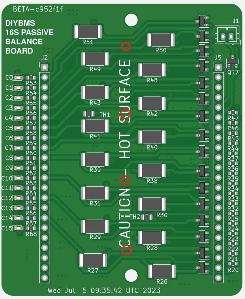
Unfortunately significant redesign!
1 Like
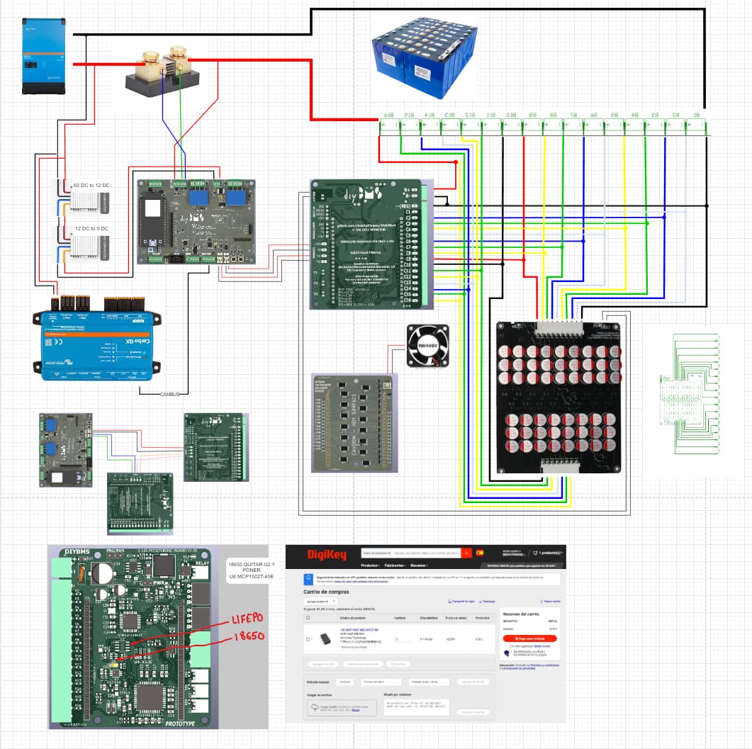
I am having a lot of difficulties to test the All in One system. I am beginning to doubt that the Lords of LSCS have made the plates well. In the end I found the signature for both the controller now with version 96b543b07407570a71adb4b8e818b83bc7d80ecf I have tested both v490 firm: the 5K and the 10K on several of the 10 All in One boards that I am preparing
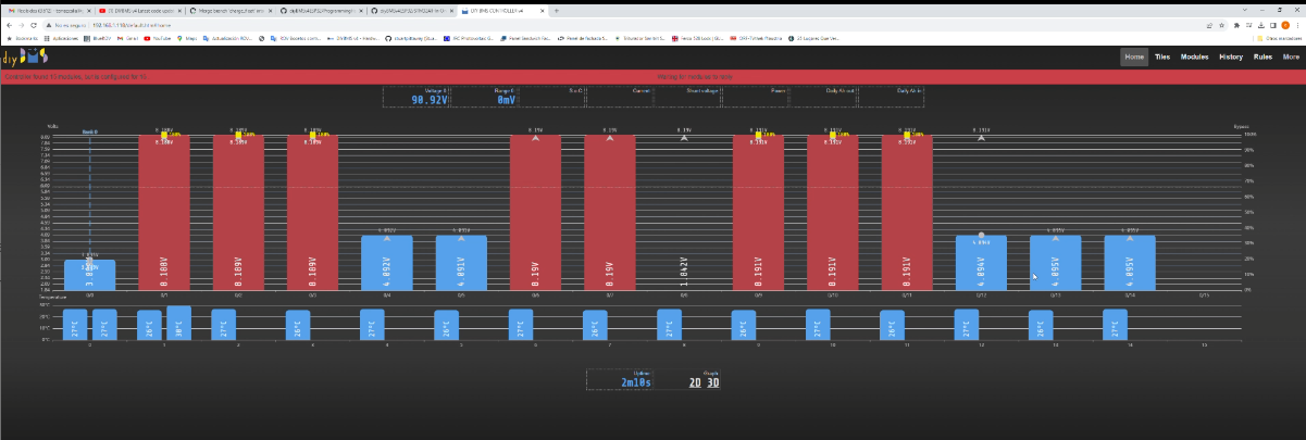
I have checked the battery connections a thousand times and in the numerous tests only a few times the All in one communicates with the controller. and in those cases it only identifies 14 cells in addition to the fact that they present absurd values, sometimes one of them 8V
have you used 16 liion at what voltage? maybe there is a problem with high voltage if they are full
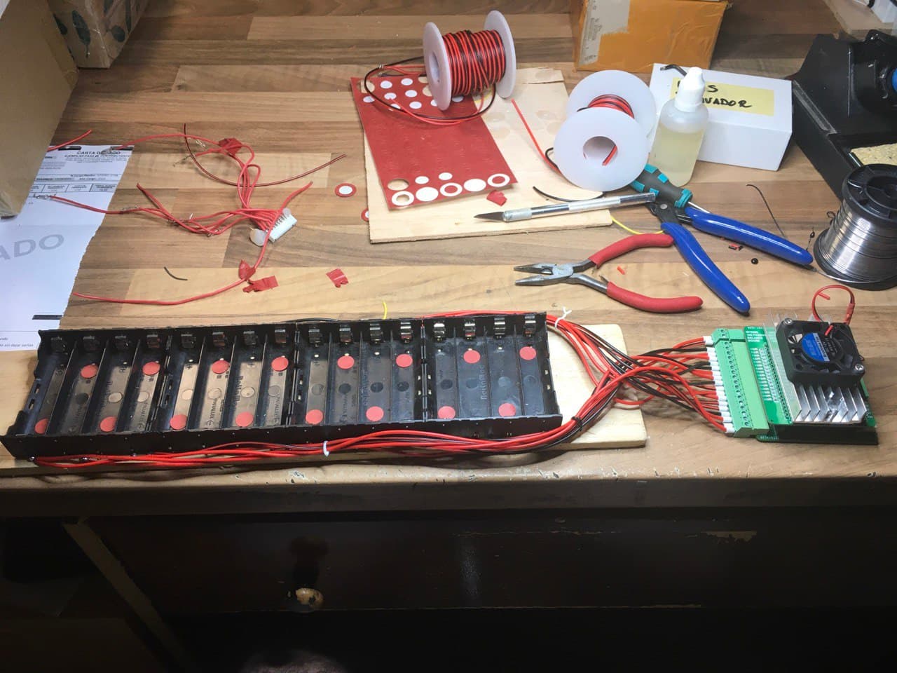
i am using 18650 but charged up to 3.5v so that shouldn’t be the problem. In the end, after many tests this weekend, including reworking the soldering of the boards, of the 8 that I have tried there are about 4 that more or less work, hopefully, I started testing 4 cells and progressively going up to one of the All in Ones that Apparently they were doing better , however when I got to cell 16 I always find the message that the system only identifies 15 cells even though it is configured for 16 . I don’t know where the problem is and if Stuart has finally tested the system with 16 cells or only with the 4 of the videos shown… The problem in the previous image already disappeared after resoldering the MAX (theoretically since it came assembled from JlCPCB it shouldn’t require this type of action) I’m also thinking that maybe I could damage when assembling some of the MCP33151, too hot when sticking them with the gun hot air? In short, let’s see if I have any moment this week and I advance in the tests. And on the other hand, let’s see if Stuart comments on the test with 16 cells that I mentioned before.
Thank you
1 Like
Hi @Chapulino
Can you tell me:
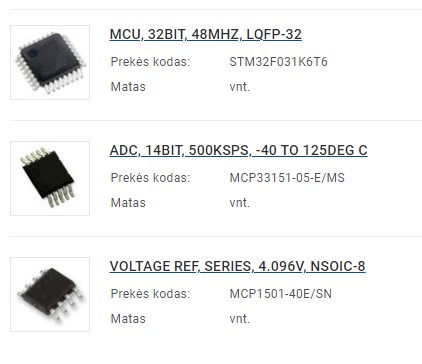
Are you using MCP33151-05-E/MS or MCP33151-10-E/MS ? (Check you didn’t use the MCP33131)
Which voltage reference chip did you use for the 18650 ?
There will be bugs in the firmware/code at the moment - hence the warnings and “prototype” status of this board.
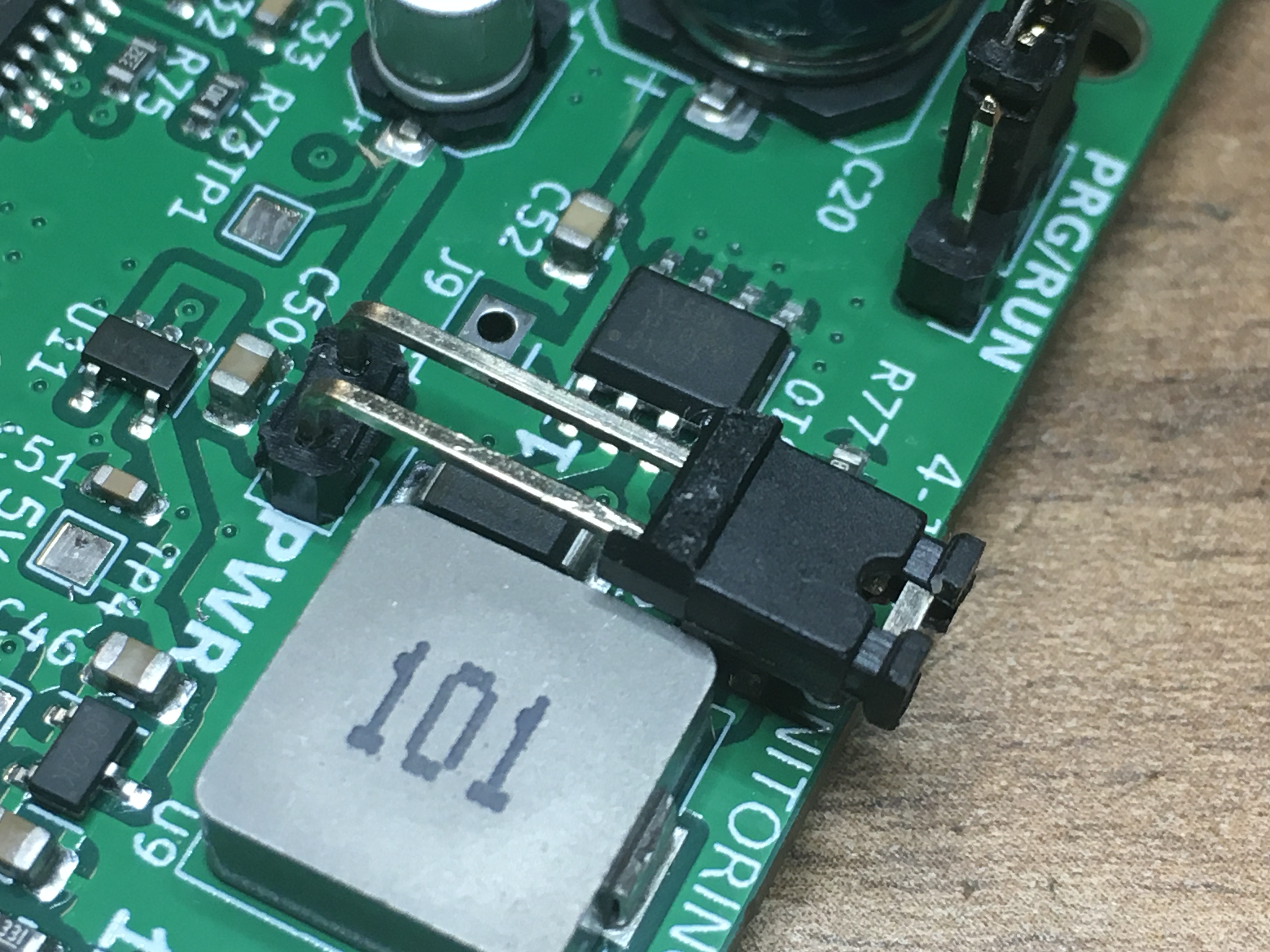
Can you check the voltages at the test points with the board powered up and connected to the cells?
TP1 = 12V
TP2 = 3.3V
TP3 = 1.8V
TP4 = 5.0V
TP5 = 4.096 or 4.500 depending on the reference chip
MCP33151-05
I am still testing with a Lifepo system, in the test module I have 18650 but charged up to 3.5V.
all the voltages are ok
Question: you have tested the system with 16 cells. Finally, I have had acceptable results (understanding what you are saying, that we are talking about prototypes) with 14 cells. If I mount 16 cells, the system identifies that it is configured for 16 cells but only captures voltage information from the first 15
hi
Not all showed voltages and cells correctly for me either, I tried 18650 14 cells and 16 cells. I thought that I burned something while connecting, so now I put it to the side ![]()
Everything was soldered and assembled at JlCPCB, except I soldered myself, I am attaching a photo
I checked everything is ok
TP1 = 12V
TP1 = 12V
TP2 = 3.3V
TP3 = 1.8V
TP4 = 5.0V
TP5 = 4.096 or 4.500
Thank you
The MCU should be STM32F030 not the F031. LCSC part number C46830.
Ok - I’ve used the MCP33151-10, which is the same chip, just quicker - so there may be some timing delays we need to double check on that one. Are the cell voltage readings completely wrong?
If you are looking at the code uint8_t queryAFE() is the function which counts the number of cells in use and then returns that to the controller.
If you want to compile the code to force 16 cells to test - change return cellCount; to return 16;
After going over the soldering that JLCPCB did on the MAX chip it worked out on some of the boards (on others I suspect the MCP33151 processor may have been degraded by my clumsy hot air gun soldering).
That problem seems solved
I’ll try a compilation but I’m very clumsy with this, I’ll tell you
thanks
[Edited for presentation - Moderator (RW)]
I’ve just updated the code to include one for the 4.5V reference chip, should be on GITUHB shortly.
Thanks for the note, I am ordering another microchip STM32F030K6T6
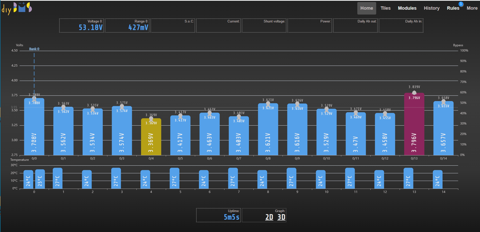
this is going really well.
For the moment, the 6 All in one that I had prepared work well, although only for 15 cells.
I only had to replace one of the MCP33151 (possibly damaged in my mount). And of course review all the welds.
This reassures me because everything seems to be some small adjustment in the software
1 Like
Thats looking more like it!
Are the voltage readings accurate? Have you built the balance board or as you going to use an active balancer?
the voltage measurements are extremely accurate, congratulations on the design.
Balance boards have been built for the 10 prototypes, and they will be tested in connection with an active balancer (capacitor balancer) but for now I am waiting to have the reading of the 16 cells.
Another detail that reveals my clumsiness, I was looking like crazy in the controller code for the way to change uint8_t queryAFE() and I couldn’t find it anywhere, when I went to bed I said to myself but yes, that is surely in his code All In One, and indeed it is there. So this afternoon I’ll try to modify the All in One programming and compile it with platformio, although I don’t know if it’s the same as how it’s done for the ESP32, well I’ll try.
@Chapulino no need - I’ve sent you a custom firmware on the GITHUB issue you commented on.