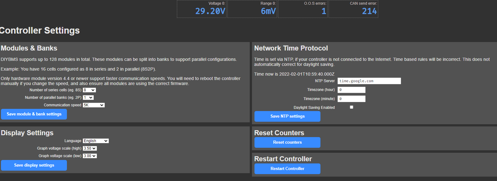
i left the comm’s speed set to the default, since its says something about not using the faster speed unless using certain modules.
Also, can I use my ESP32 controller to program my cell modules if I don’t have a SD-card slot installed on my controller? I used Platform IO to program my cell modules since I assumed i needed the SD-card slot in order to use the controller. (maybe I flashed them with incompatible/older firmware?)
*EDITED
seems that not having a SD-card slot shouldn’t matter. I’m going to try to flash them again now using the ESP32 controller and see if that fixes the issue.
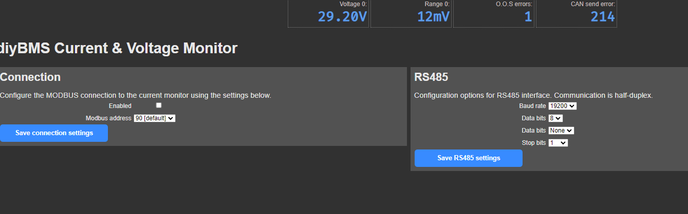
thanks stuart, I seem to vaguely recall this screen, thing is how do I get to it???
is it a one-off when setting up the thing and I somehow now need to trigger it?
my current monitor settings screen looks like this:
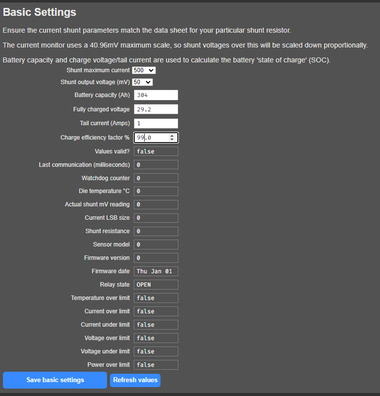
thanks stuart, BUT once I fit values there (well try to fit all on the basic tab) and hit save I get a window with all the info empty/zeroed. Is it because I add all values and there’s no response from the system?
Mind when I enabled it, it came up with blank values as well, although canbus was reporting this 8Ah.
Ok, not really sure whats happened there - it won’t save the values correctly as these are sent to the shunt. Didn’t really expect people to use the Victron interface without the shunt, as it doesn’t really add much value.
no worries, should have a shunt next month so all should be OK then.
If I may (following my 2day experience next to my 304EVE cells and charging/top balancing them) one more Q.
For top balancing I see that the system can cope up to 1.2, max 1.3A coming into the bank. That the lifepo4 balancing cells (with I believe slightly larger resistors) can pwm nicely and keep temps below say 60 or 65C.
Cope as in keep cell V at bay and within 10mV from set limit which will be more than enough in operation where I wont be at the limits but charging at 3.5V per cell max
So in theory should I also instruct my victrons that on balancing mode it should restrict charging to this value?
Although it seems little, it does makes sense, right? or am I missing something.
quick yes or no (with pointers to what I should study) is fine
got the cell modules communicating with the controller now!!!
as soon as i used the controller to flash the modules, everything worked fine.
Not sure why flashing them thru platform io with a usbasp wasnt working but… i tried both the diyBMSv4ESP32 & DiyBMSv4Code repositories… (kinda confusing)
@stuart
also have you or anyone came up with alternative IC’s to replace the one that are on the Current Shunt BOM that are impossible to find due to the chip shortage?
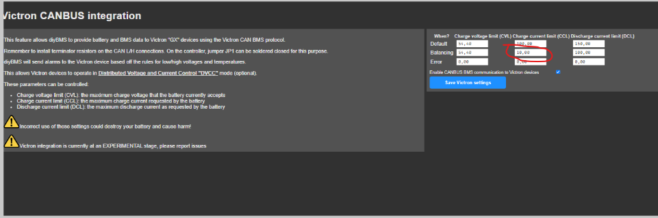
when you use a DIYBMS system in conjunction with the Shunt and Victron, when a cell starts the Bypass, the charge intensity to the value you have preset here (in my case 10A),
On the other hand, cool the modules even if only with passive cooling example helps to balance with fewer interruptions to reach the maximum temperature.
Another issue with a system very similar to yours 16s 2p 305Ah CATL cells from 3.4v it is very difficult to keep the pack balanced even if they are new, and from 3.45v it is practical to avoid large deviations because it is the nature of the chemistry of this type of batteries, at least from my experience, despite a range of use up to 3.45v maximum, protects the degradation of these batteries, giving them a long useful life and does not impact too much on the available capacity
thanks I know where the value is, wondering if it makes sense to drop it THAT much to 1.2A. Since they are lifepo4 and will be slightly crammed behind a sofa in the boat not much of a gain to be had by blowing air in a relatively confined spot. will try it though and see, or could order 24 heatshinks and fit 4 on each module
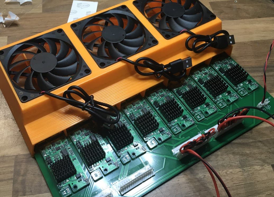
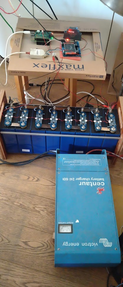
8S EVE 304Ah cells with 20mm ply endplates bolted with 4 M8 bolts threaded in a transluscent plastic hose so that there’s no metal touching the casing. There’s a 2mm piece of industrial rate rubber in between all cells. On the carton above the bms, 2.5A power supply, a raspberry pi 4 and a PEAK-CAN can-usb adapter. Raspberry runs VenusOS and communicates with the rest of the Victron systems onboard (that’s obvs the test system at home, another rpi is already onboard with the Victron Multiplus and MPPT and NMEA2000 operability).
Using the old 24V 60A Victron (unintelligent) charger for the testing and a 2kW inverter I’ve borrowed from a friend.
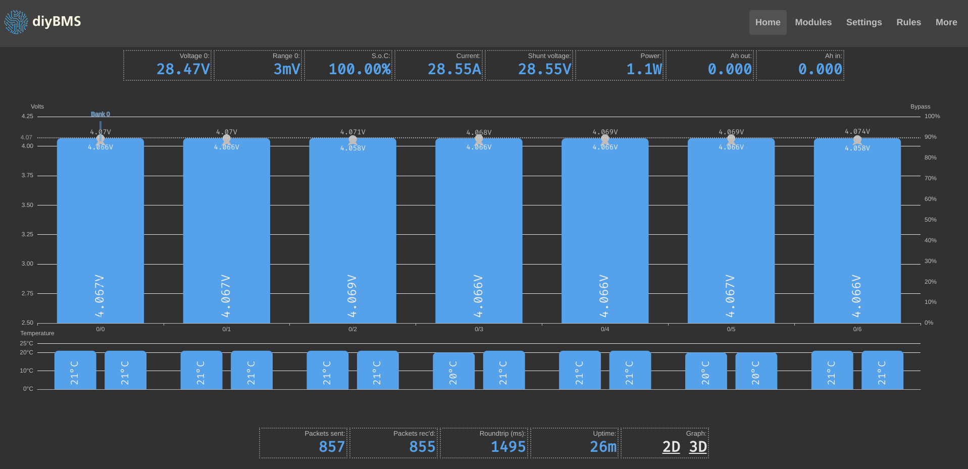
Currently on the second full charge/balance at 3.65V per cell. Charged with the Victron which tapers off and stops at 28.8V (very convenient) and then a small bench powersupply takes over to do the final part up to 29.2V limited to 1.2A. Cells start balancing and after an hour or so there’s no demand for current, process stops.
Charged at 60A (theoretical, 55A with my uni-T ampclamp)
Discharged at 46A, on the first attempt managed a solid 6.5h of discharging at under 0.2C Attained curve (influx/grafana) is v.close to the published data by EVE. Waiting for the bits to arrive to built a shunt and have a better idea of the SOC.
Currently relaxing and dropping to normal idle Voltage.
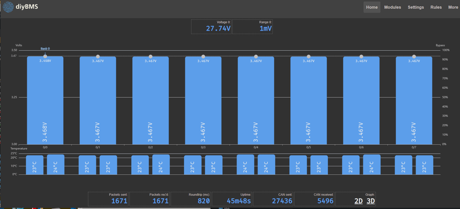
Wonder if anyone can better the Voltage Range of 1mV on an 8S system
Ranges from 1-5mV over the last hour I’m checking.
Calibrated the modules in the morning after letting them relax (half charged) overnight. Had small variations to sort, nothing massive - less than 30mV iirc.
More testing, checking the DVCC options and generally messing about. Probably install it onboard mid/end February.
thanks to @Bill.Thomson I was finally able to get my grafana dashboard set back up on my Linux server last night.
But it seems that the only information that the controller sends through influxdb is cell voltages, temperature readings, and current readings. Which is all inside the cells measurement that gets sent to my database.
But on github, @donnib has a section about setting up a grafana dashboard and somehow he’s able to get data about what the relay states are and all the rules of the esp32 controller…
Is my esp32 controller supposed to be sending that data to my influxdb database normally and for some reason its not? Or is he running custom firmware in order to get that information? Or am I missing something completely?
Any help would be greatly appreciated. Thanks a lot
Hey Bill,
Thanks again for your help getting my INFLUXDB and GRAFANA dashboard all setup. Again… LOL
Everything else went well. no real problems getting my dashboards etc. all set up.
The only thing now I’ve been trying to figure out is, being able to pull up my dashboard simply and easily on my android device… Very strange but Grafana doesn’t have a android app etc… There is a unofficial Grafana app on the google playstore but for some reason it doesn’t work. Not sure why the developers haven’t fixed it since the app is rated 1 star from everyone that’s tried to use it…
the only only option i have at the moment is to save a chrome bookmark on my home screen and view the dashboard that way… But of course the scaling etc… isn’t correct and its not very appealing…
had a discussion on ybw forum with fellow boaters. One issue that comes up often is monitoring how many times the bank has “cycled”
Granted, cycle is a fairly vague term that may mean anything but let’s not get into that.
My question is, how easy is it to log all Amps (or Ah rather?) going in and coming out of the bank and keep it in the SD (as well as present it on screen (OK, that bit is easy)
Is there such a hook? Was thinking of presenting that info divided by the Ah of the bank as a rough indication of “cycles” done by the bank.
Makes sense, should be easy I guess.
Stuart if you want I can raise an issue in github for that as enhancement.
Another issue I have is victron canbus specific will raise an issue straight away.
That data is currently logged to the sd card, but it won’t be a running total of all time - it gets reset when SOC is 100% - however using Excel or similar you should be able to get a total.
thanks Stuart,
checked the data logged on the SD card. I see there is mAhIn mAhOut and power.
I guess in order to have an indication of the 'wear" of the bank I’d like to have an overall recorded “usage” so, could focus on mAhIn alone and every midnight, twice a day, once an hour or whatever send the incremental input to my influxDB. Then I can process that and have an overall MAhIn for the bank
The trick would be to keep that daily input separate from resets/crashes/previous day input.
The easiest approach I think (and I’ll try it soon once I get all the bits for my current monitor!) would be add relevant code in the influxdb.cpp record on an hourly basis mAhIn in a custom variable (reading from the currentMonitor.modbus.milliamphour_in), sent to influx, zero this variable and loop. Will also have to figure the trigger for the reset, so that I don’t miss much but tbh at 1h intervals it wont be ground breaking errors.
Wouldn’t really like to use the sdcard for that, logging at 15-30sec intervals should kill the sd card pretty quickly. Every hour should be better, dunno.
From experience on another raspberry I have for my home automation system, 5yrs was the max for the card on fairly relaxed logging pace.