sorry, Mike, updated the github, didn’t mention anything in here.
Found the issue (at least in my setup- but I don’t think anyone has noted such a problem!) being lack of GND wire between the PEAK-CAN USB controller and the diyBMS controller. Was only using CANL and CANH…
Added it, CAN now rock solid even plugging and unplugging USB and serial connectors.
Still influx seems flaky but testing further.
Without the GND connection the CAN-H and CAN-L are floating and can cause anomalous reads. It’s part of the CAN standard to have a common GND reference IIRC.
But good that you found the issue with your CAN adventures.
should have known that…
got suspicious when I realised that crashing was mostly related to me trying to charge the batteries so abruptly altering the setup (or so I thought)
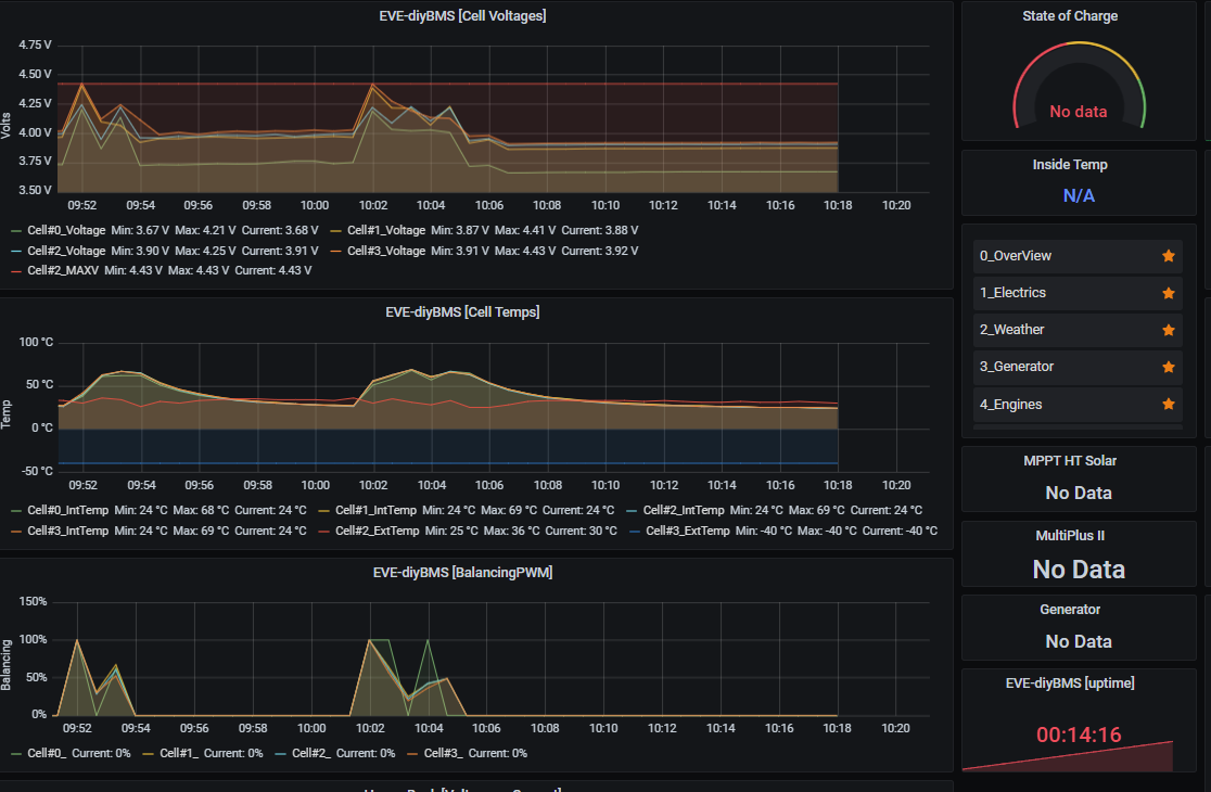
Wonder if this also related to influx failing as now with 40sec posting and double the data posted it’s up and running for over 14h! even sorted uptime on my grafana panel:
assume you DONT want to use a contactor that needs to be powered on all the time when batteries are active, or don’t want a NC contactor (doesn’t sound very much failsafe tbh) then you come up to latching/bistable contactors like Bluesea or a few more.
They typically employ a 3wire comms one common gnd and a +12V (or +24V) either side as a pulse to close and open the circuit.
Even using the pulse and NC options of the rules, I don’t really see how this is going to work unless rules are reworked as the above approach means you need two relays (say #1 and #2) to pulse on and off the contactor (trigger and reset values). Am I missing something here?
Say rule: Individual cell over voltage (mV)
would need relay #1 pulse to activate rule (disconnect contactor), but relay #2 pulse to deactivate rule (reconnect contactor)
It’s possible but I think a bit unlikely. There are a few issues with the InfluxDB integration that have yet to be resolved, they are exasperated by high frequency HTTP calls which can lead to the LwIP stack crashing due to lack of buffer space, which is ultimately what causes the ESP32 to restart.
left field Q
on this last run (going strong touch wood for 19+h) I’ve removed the touch screen as I wanted to fiddle with the dip8 can chip and thought I’d run without it. Could the lack of screen help in buffer allocation/space?
It is possible, but likely not too much since all background tasks (TFT, CAN, RS485, etc) are all allocated/running regardless of being enabled. It’s one area that the BMS can use improvement in.
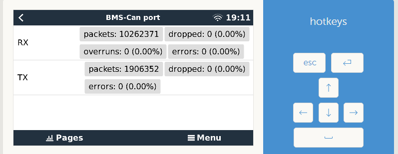
The OOS errors and Packet Failed messages look like a bug in which the BMS sent a packet out (or at least tried to!) and didn’t get the response it expected. Likely the Packet Failed message should be expanded upon with why it failed.
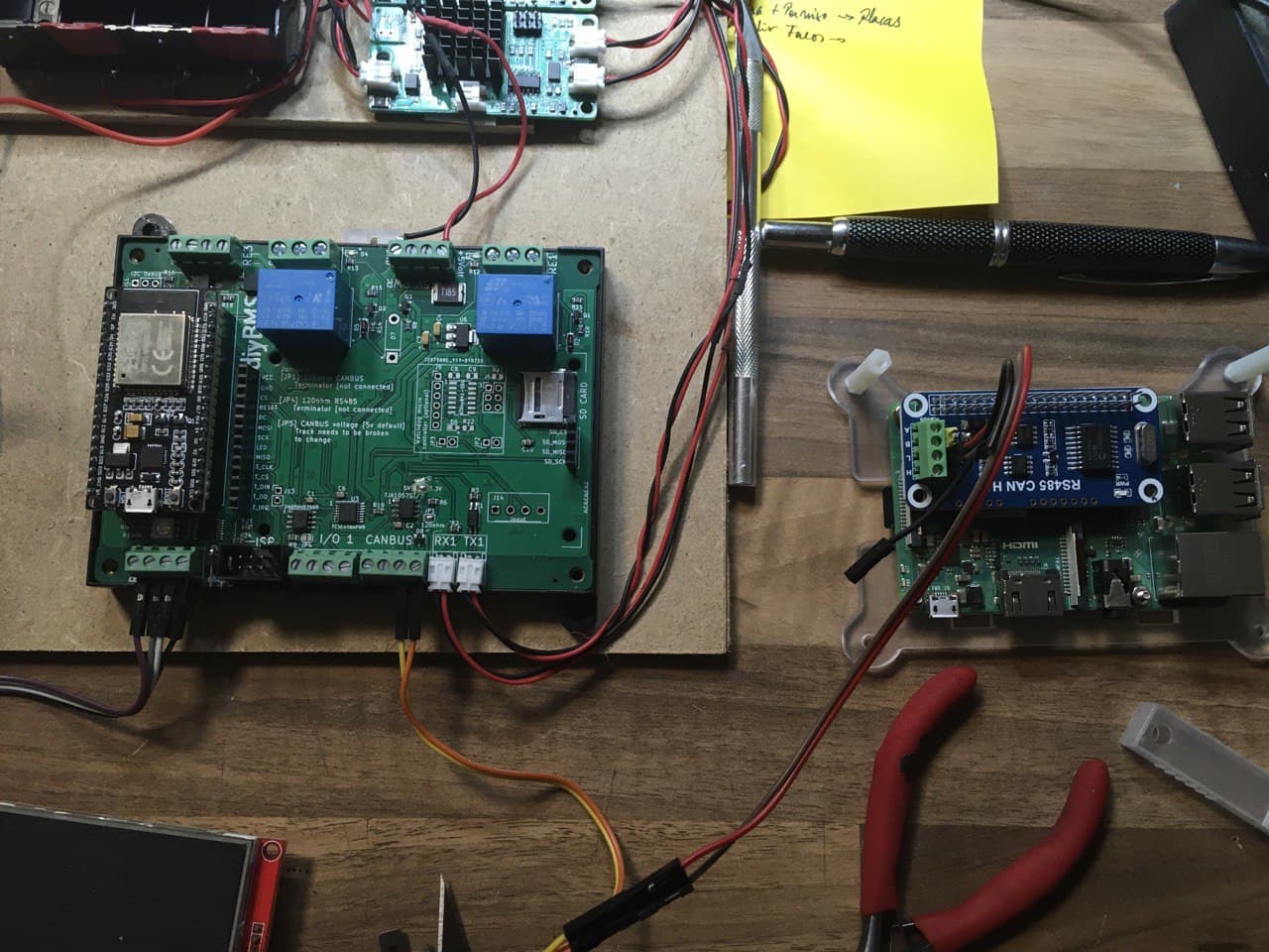
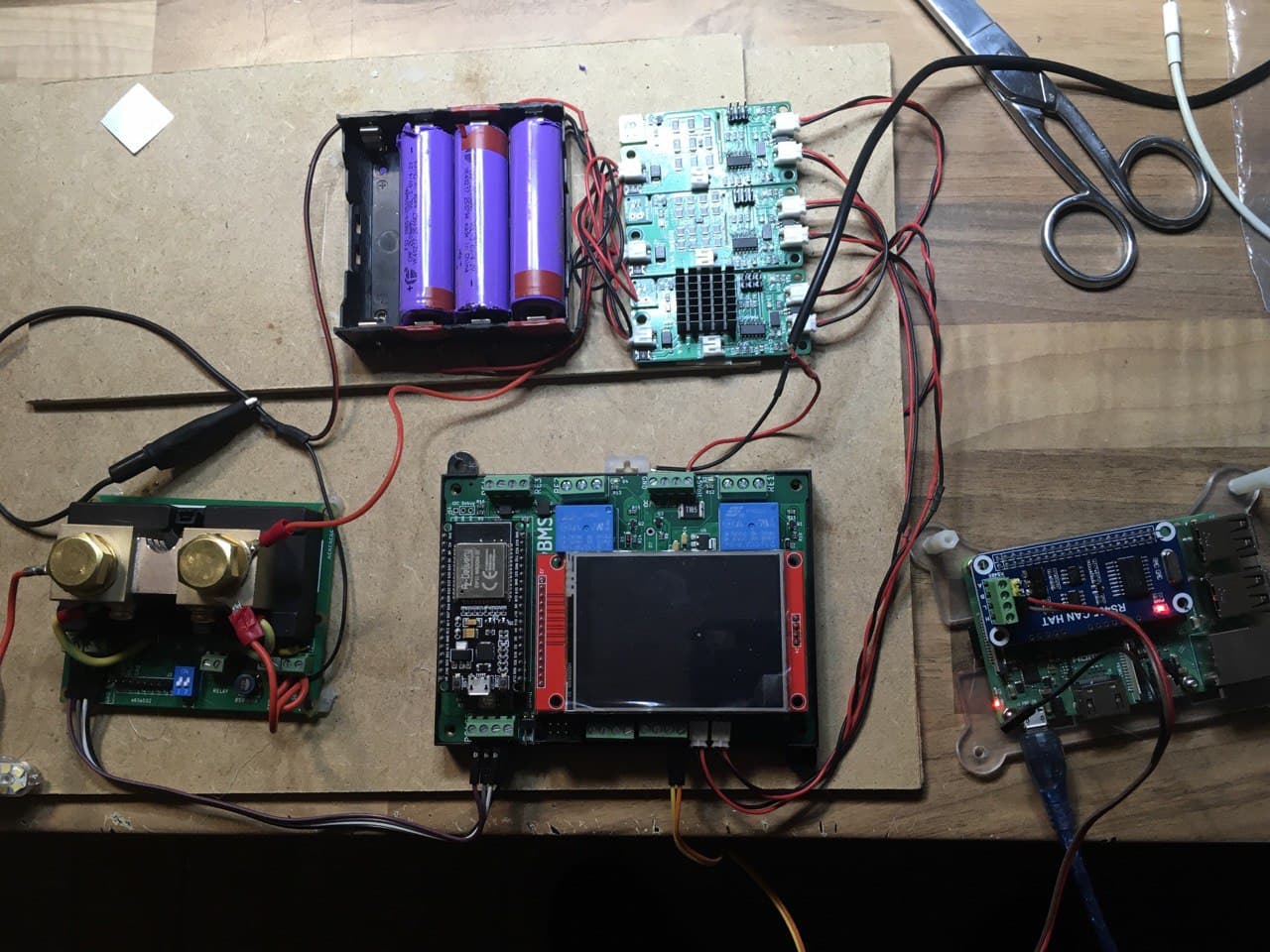
In my test system I am experimenting with a raspberry with Venus OS and a CAN HAT Waveshare. I think I have configured it correctly by following the instructions at GitHub - kwindrem/VeCanSetup: Manages Victrion VenusOs VeCan (aka CANbus) ports
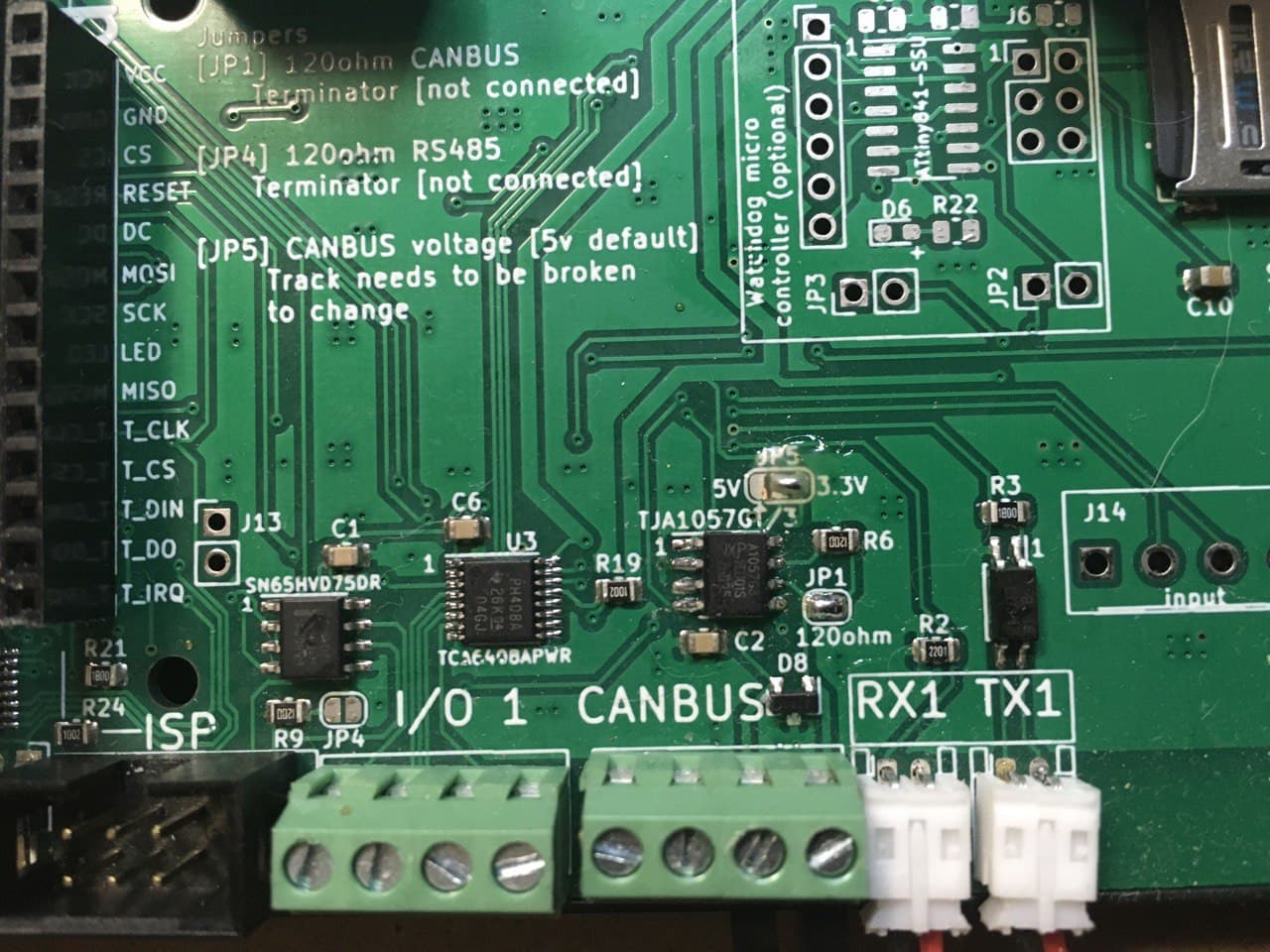
As for the controls I have cut the 5v cambus track and I have closed the bridge to 3.3v (the voltage that the CAN HAT supports is 3.3. Is this correct?
Well at the moment I can’t get communication that may be happening, how should the channel and can h be connected between the controller and Can HAT L with L and H with H or should they cross?
no cross H to H L to L, need GND as well (don’t connect V+!)
further mine is running at 5V, why did you change to 3V3?
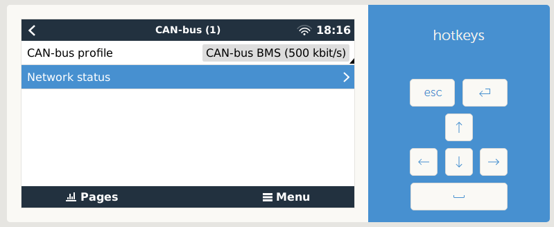
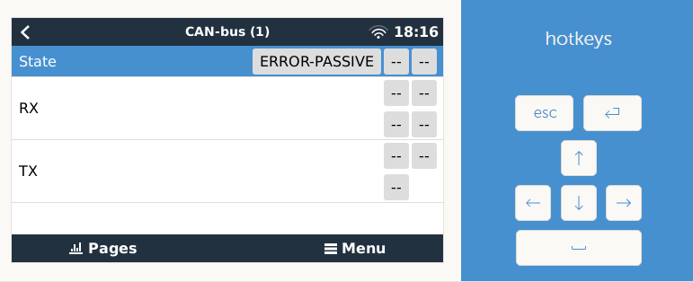
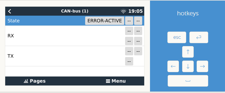
show us the rpi screen on Settings/Services/can(1) please
should have CAN-bus profile set to CAN-bus BMS(500kbit/s) and Network status should be ACTIVE. Mine always is ERROR-ACTIVE but it’s OK
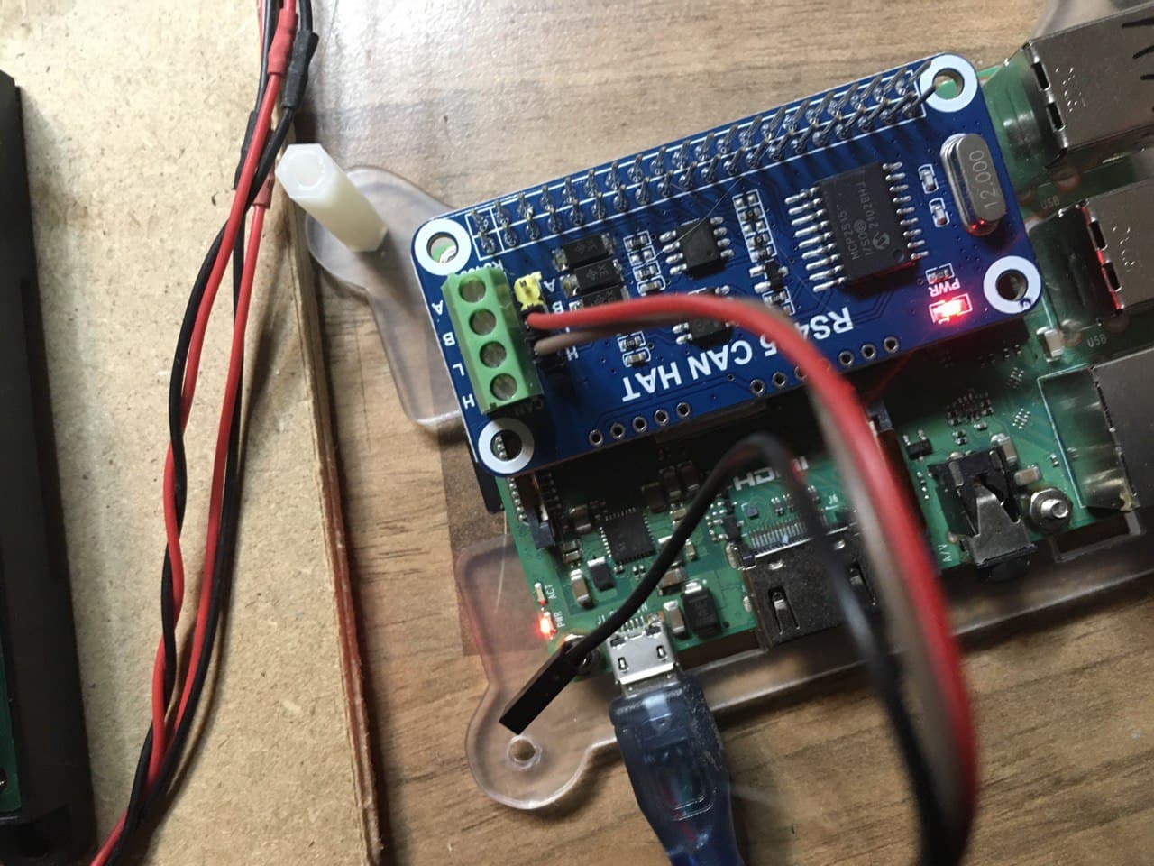
I have put the cambus bridge back on 5v. verified HH and LL this is the captive victron screen to connect GND I don’t know how to do it because the CAN HAT only has HL where I could connect the GND of the CAN port of the controller with the Raspberry?
connect the black (GND) to the relevant rpi pin - on the two lines of pins on the top of the pic there are 3-4GND points, just choose one!
ERROR-PASSIVE means it’s not communicating!
Reboot a few times, rpi first, then controller. Do not charge the batteries when starting the whole thing up (had issues on mine maybe not relevant but you never know)
edit: typed while you edited yours it seems. So has the network status now changed to ACTIVE?
edited again: I have exactly the same CAN/RS485 HAT. I see yours is the 12MHz crystal, make sure you have that in your config.txt in u-boot/ There are two options on Kevin’s installation for WAVESHARE.
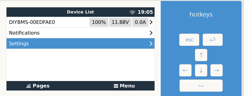
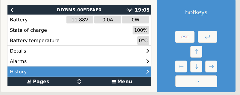
It is strange, in this tab I have an error but nevertheless in the main one I have the data of the complete DIYBMS (I have added GND but I do not see changes)
It is also true that in the tests I do not have Victron or ESS therefore and the configuration perhaps makes the can of the test facility not see it as a battery
that’s how mine is as well.
Now started charging/discharging and testing settings. You’ll see a fair amount of warnings, want to understand it a bit more in code and discuss it:
One issue is that once even a single cell is balancing, Victron comes up with a warning “cell imbalance” which is not really that. Wonder if it would be better to edit the code in victron_canbus.cpp to only sent this warning when there’s indeed imbalance in the system. It looks like there isn’t another warning for “cells balancing” and Stuart got that in first. Reason I’m mentioning it is that practically a large part of the charging cycle you get this warning which is not v.helpful (imho)
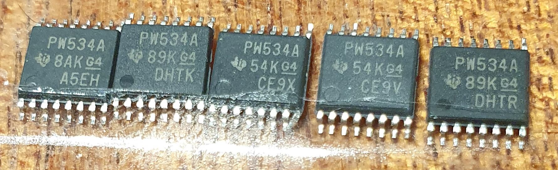
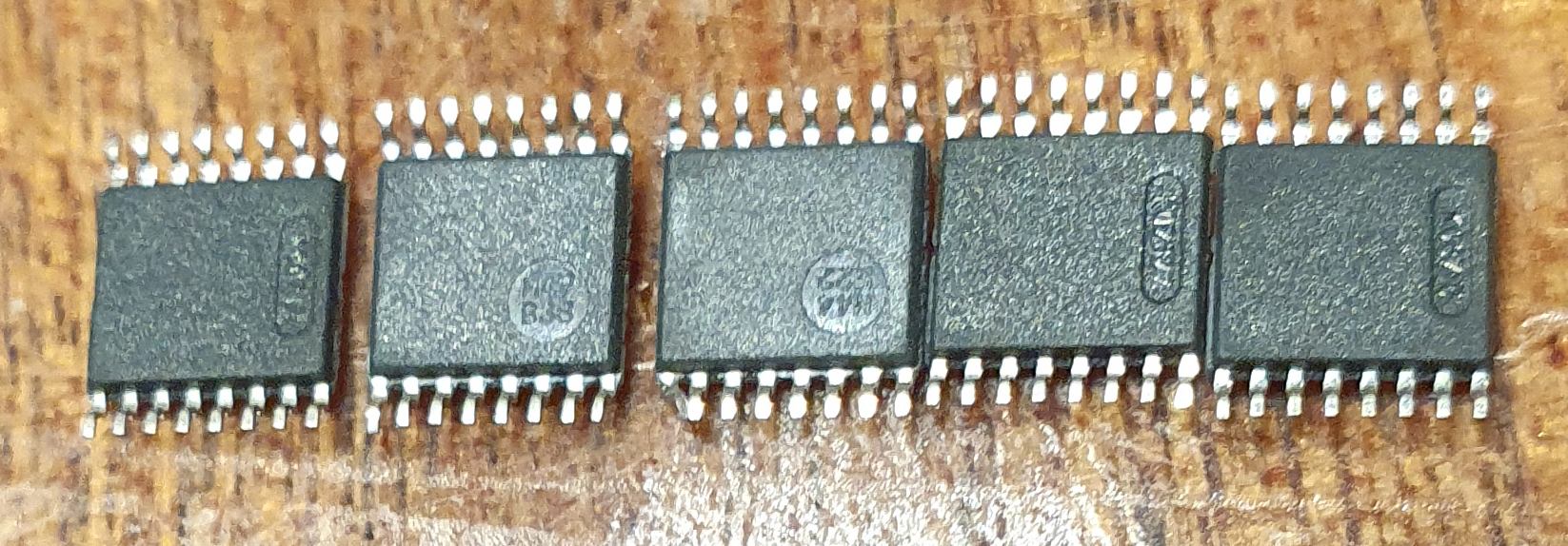
Looks like rejection, production date and production code all are different, not on plastic tape just in zip lock bag, contacts are little bended, but cheap and works. At aliexpress in search string type “1005002164280518”.
the canbus error is a bug i have it too
i have the dual can hat it works fine on both ports
i havent cut anything on the controller just added a 120ohm resistor on the clamps outside because i can not reach the internal resistor selector in the din rail case
assuming you can compile and upload new code to your controller, open influxdb.cpp and replace line 102 (which is basically the first of the following lines bar the addition at the end) with the following two lines:
what that actually does is add in the cells v, i, e, b datastreams a p which is the pwm of each cell. Reason being that mapping on grafana the b datastream which is a boolean true or false when said cell is balancing or not, is not v.easy But mapping the PWM value from 0-100 is much easier (for a non-programmer at least)
second line adds systemVAR → uptime in seconds.
compile upload, done.
now on the grafana side, not sure how I can export a dashboard tbh. If someone explains happy to do, but building it seems straightforward to me.
NOTE: above code is rather rough (OK, very!) will hopefully sort it out over the following days and come up with something better.
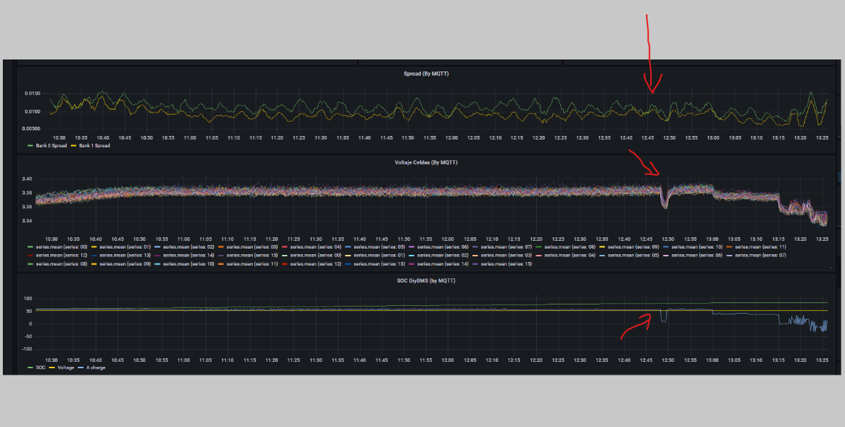
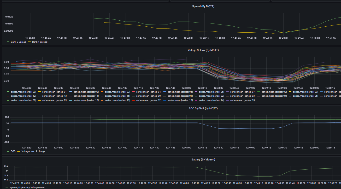
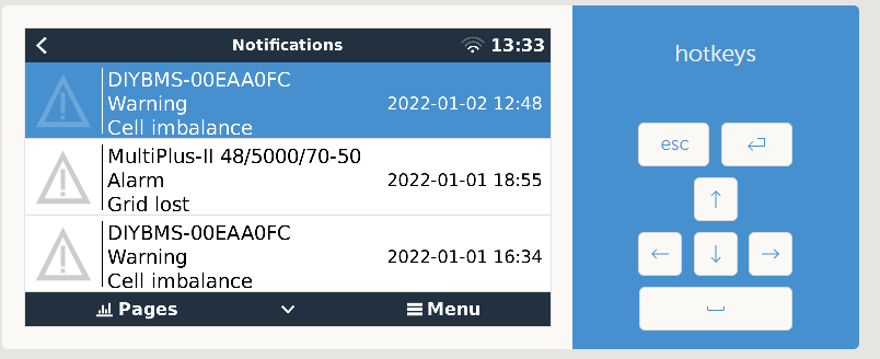
Hi Stuart, I have been controlling the battery through your shunt and the CERBO for almost a month. In this time, it seemed that when the battery is charging for example at 60A and DIYBMS communicates a Cell Imbalance alert. The charge is then reduced to 10A, a short time elapses and then charging is resumed at 60A. The question is, where is the unbalance level that triggers the 10mV alert? more ? , can this parameter be adjusted?
As can be seen in the attached graph, the battery was charging at about 50 or 60 at 12:48 a Cell inbalance warning has been produced, but as can be seen in the Spread graph at that time an unbalance is not appreciated significant