On a 4.0, its likely to have wiped the ATTINY chip - you may be lucky and be able to reprogram it.
If not, its likely fried.
On a 4.0, its likely to have wiped the ATTINY chip - you may be lucky and be able to reprogram it.
If not, its likely fried.
So I’ve narrowed it down a little bit about not being able to save changes. It seems to happen only in the Google Chrome browser on Android or PC.
I tried using Internet Explorer or whatever it’s called now in Windows and that seemed to work just fine. No issues at all saving changes.
But since you asked about it rebooting frequently, I do notice that sometimes the webpage is not immediately available or if you’re on the web page sometimes it goes kind of grey and is trying to refresh and takes 20 - 30 seconds once in awhile (quite often)
*using Esp8266 w/ latest firmware from Github
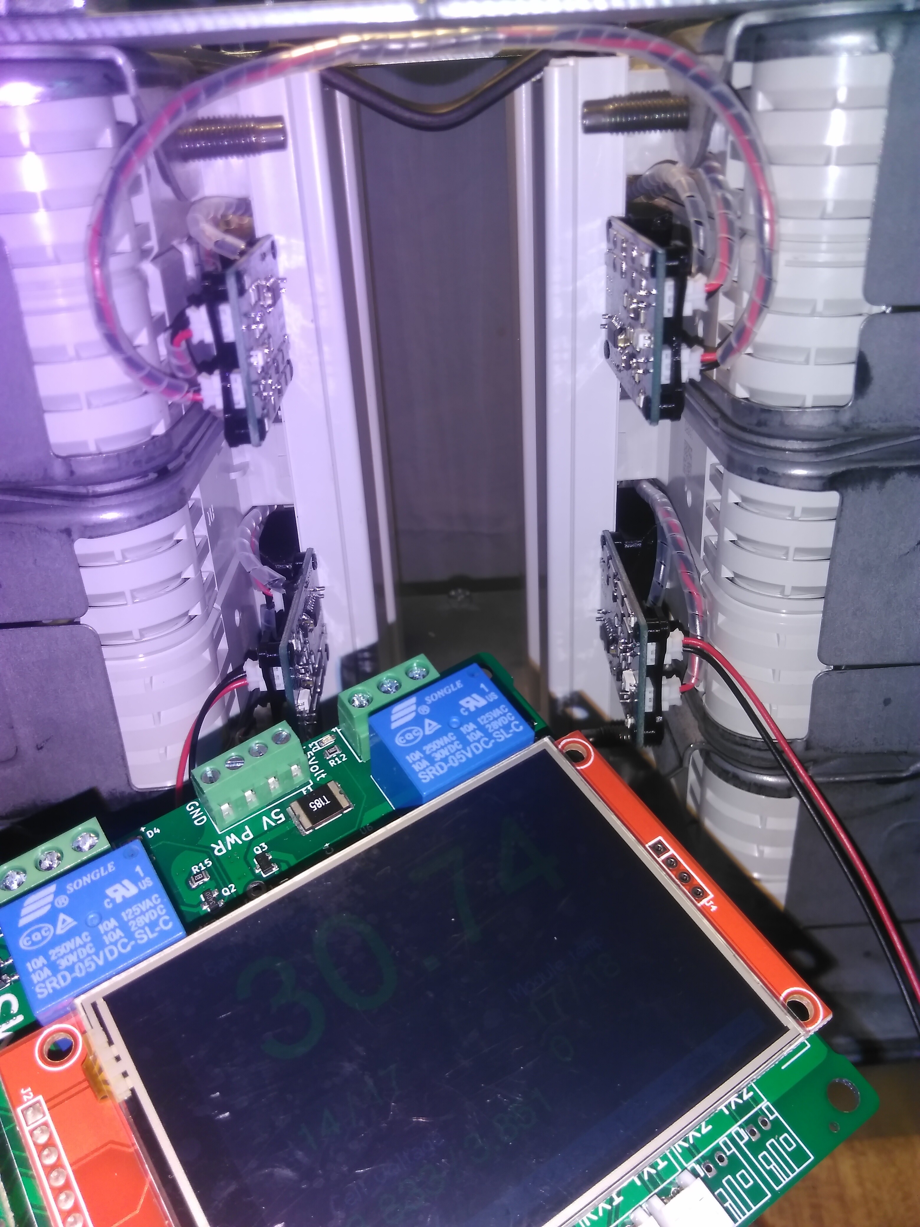
Finally got my lcd, bought it from ali 15.03.2021 and the seller “forgot” it (always film opening packages or they will get you), then from your affiliate 31.03.21 link to become out of stock after 1 week and every day they push the date another day or week.
After that another ali seller and 10 days later it’s here…
Is it just me or the backlinght is too dim?
Howhard would it be to add temperature calibration? my sensors are all over the place 
I also noticed this sometimes it can take several minutes up to 20-25 until the website becomes available. Most of the times I noticed when changed clients.
Do you have a strong WiFi signal near the esp8266?
I’ve seen problems with frequent reboots caused by low current power USB supplies, especially when accessing WiFi.
Hello @stuart
I have this Wemos D1 mini Pro.
I followed you instructions on your youtube video, but when i try to “Upload Filesystem Image”. i get this error:
Building in release mode
Building file system image from ‘data’ directory to .pio\build\esp8266_d1mini\diybms_controller_filesystemimage_espressif8266_esp8266_d1mini.bin
/readme.txt
Looking for upload port…
Use manually specified: COM3
Uploading .pio\build\esp8266_d1mini\diybms_controller_filesystemimage_espressif8266_esp8266_d1mini.bin
esptool.py v3.0
Serial port COM3
Connecting…
Chip is ESP8266EX
Features: WiFi
Crystal is 26MHz
MAC: e8:68:e7:80:9f:64
Uploading stub…
Running stub…
Stub running…
Changing baud rate to 250000
Changed.
Configuring flash size…
Compressed 3121152 bytes to 3298…
Writing at 0x00100000… (100 %)
Wrote 3121152 bytes (3298 compressed) at 0x00100000 in 0.1 seconds (effective 176097.4 kbit/s)…
A fatal error occurred: Timed out waiting for packet header
*** [uploadfs] Error 2
================================================================================================== [FAILED] Took 33.65 seconds ==================================================================================================
Best regards,
Ako
Rather than follow the YouTube instructions, I made a simpler way to program the chips.
Take a look at the instructions on GITHUB
Hello @stuart
So you don`t need “filesystemimage” added anymore? Even if you are uploading code through VS Code?
Now i have another problem. I added 1 module to my controller and 1 battery = 3.57 V. On the page it shows 1.336 V. I tried to change the “actual measured voltage”, on the page, but it changes back to 1.336V. I tried different battery`s with different voltages, but on the page it shows 1.336 V
I have v4.4 module
Best regards,
Ako
Which modules do you have, and what code did you program them with?
I have v4.4 modules and i uploaded V440 code using VS code. I uploaded the same code on to the second module and the results are the same. It also shows me error that it detects 2 modules but is configured for 1?
That error simply means you have not told the controller how many modules you have installed. Just change this on the settings page.
@stuart your work is great addition to DIY world, thank you for your hardwork. one step closer to my power wall.
quick question: do we have that LCD model number or link ?
i think i can reply to my own question,
It should be in the BOM file on GitHub, it’s a TFT display from Banggood.
Last time I looked it was out of stock.
@wasim
Below is a link to Amazon (USA) for screen that I purchased and works fine.
They’re made by countless manufacturers.
You can just search for: ILI9341 2.8" SPI TFT LCD
He’s the one I got from Amazon Prime:
Finally received my ESP32 controller pcbs from JLCPCB. (Took over a week for before they were shipped for some reason)
Got them up and running yeah, everything seems to be fine.
Question:
How would I go about creating my own custom splash screen for the LCD?
I can imagine it’s somewhat a involves process. But I was hoping maybe you could point me in the right direction.
Is the initial boot up screen saved as an image in a particular file etc…?
Thx
splash image is in ESPController\include\tft_splash_image.h file
you can use GitHub - sparkfun/BMPtoArray: Python script to convert a bitmap to an Arduino prog_mem array for outputting grayscale images to OLEDs. to generate your own,
That screen looks fine, watch out some don’t have the touch interface!
Thankfully the linked TFT appears to have the touch IC (U2) in the picture. @Jon_Coop make sure U2 is fitted on the TFT you received.
Only the logo is static - the text that is displayed is drawn via the code.
The logo is in the file named “logo.bmp” in the “web_src” folder. It needs to be a 4 bits per pixel BMP file.