I don’t have my batteries in yet, so I have no real test environment. Does the battery voltage absorb or relax a little after charge? For instance, if a relay rule is set for triggering at any cell reaching 3.50 volts, when this is achieved and the charger is immediately disconnected, will the cell likely drop to 3.49 volts, thus going under threshold and releasing the relay?
I’m kinda new to writing rules and sketches ,but could you not write it to trigger at 3.5v and not release until say 3.4 or whatever?
in the testing i have done with these cells,in my case they do relax a little depending on the rate at which they were charged/discharged.
Chris: If I understand you correctly, that would require an “If - Then” type of relationship. Although the rules have priorities, I am not sure they can build upon one another for example, if Relay 4 is energized, then energize Relay 3 when voltage level is under 3.4v. That is certainly doable, but I suspect that the relaxing of the voltage will solve my issue, which is restoring the relay to unenergized after charging. Theoretically, if I manually initiate charging, a looped, or self-powered NO relay will keep itself energized until the DIYBMS detects 3.5 volts on a cell, at which time it will energize a NC relay and disconnecting not only the charger input, but also the looped input. After a few minutes, the cell relaxes to less than 3.5 volts and the NC relay de-energizes. The only way to restart charging, for my situation, is to manually close the contacts.
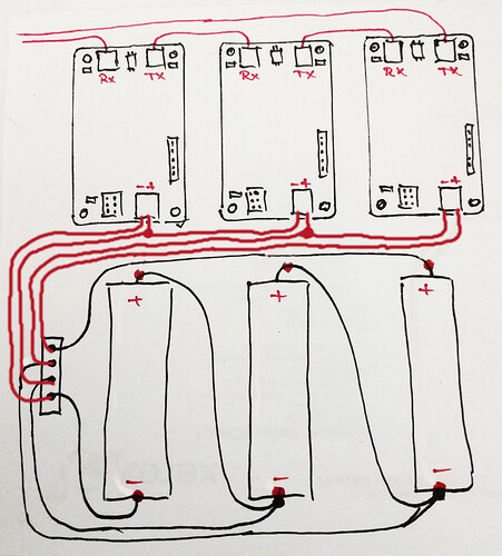
How do you guys wire the DIYBMS to the cells connected in series? Because for sure I’m doing something wrong, I manage to kill another module ( even with Wemos powered from a different power source) . Here is how I connect them.( I edited the drawing to be exactly how I use it)
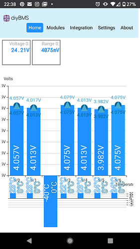
And this is how module 3 is showing up the voltage and temperature now :))) when I connect a load I’m getting the green led always on at random on some modules, disconnect the cables to the cells and is working after that until I manage to damage the 3rd module.
I’m testing my modules after building them and I’m getting intermittent results. I’m just checking a single module at a time first. It seems to take a long time before the controller recognises it and then it will work for an hour or so and then disappear again. The same thing happens when I try another module in its place.
I’m also trying to debug with the serial monitor in PlatformIO and I am getting no output whatsoever. I’m not familiar with the swap() function but does that change the pins so I can’t use USB to see the output?
Ok, so it appears that if you reset the ESPController config then you have to reflash the ATTiny module
Marius: I do not see anything wrong with your cell monitoring wiring.
Thank you for taking the time to look over my post Jeff, I was sure that is ok but I’m not getting why the modules are behaving like that and the module no. 3 is dead ( not completely, is still reacting like a good module only that in software I’m getting the negative voltage blue bar and -40 degrees on the temperature, I even reflash the module and I didn’t get any errors but is still acting the same way ) I think I damage just the voltage reading pin from the Attiny 841 or the LM4040 as I don’t have temp. reading also.
The strange thing is that nobody is complaining about this, I read again all the post’s and even go throw the post’s from the previous DIYBMS version and I don’t see something like this.
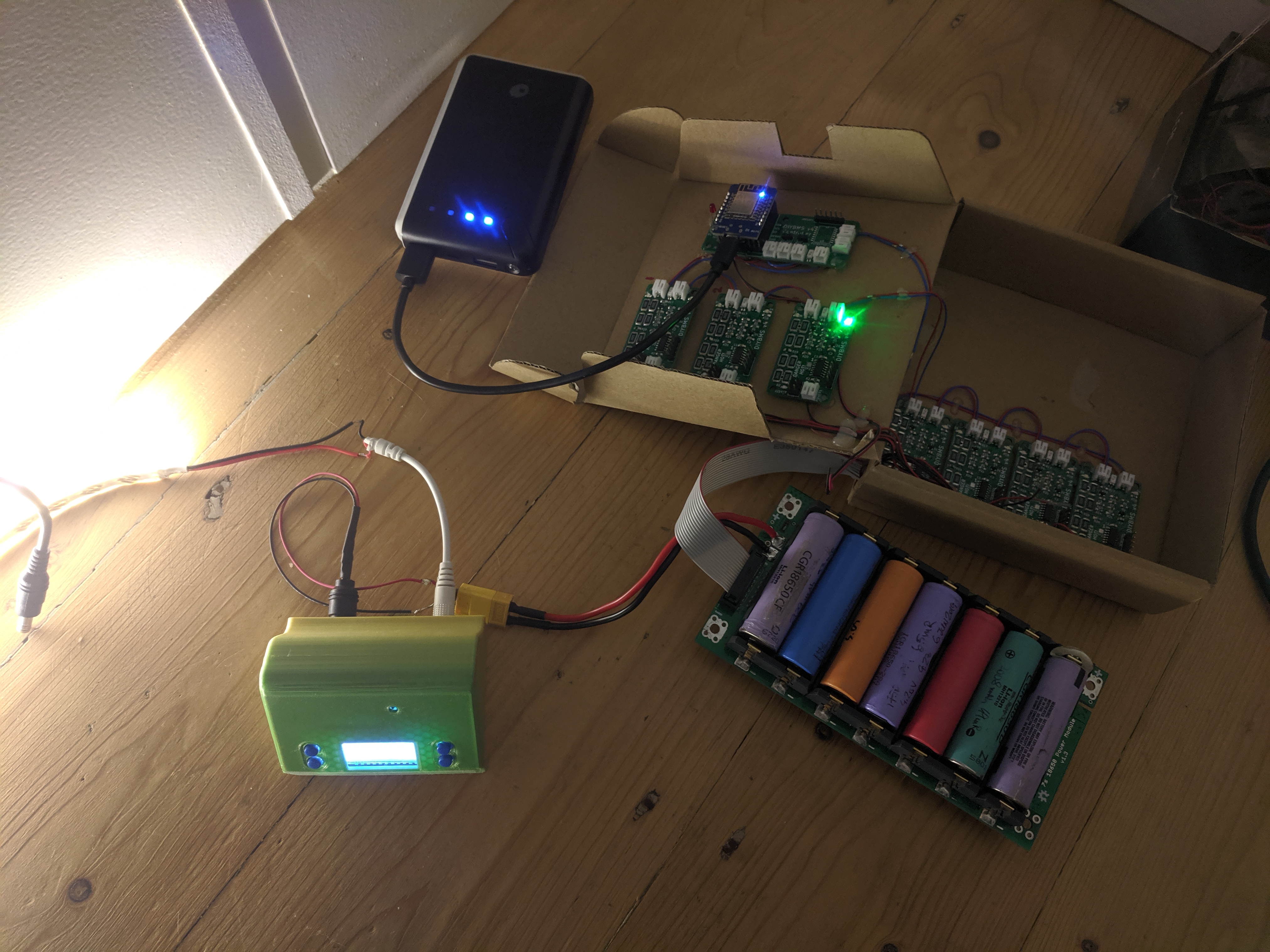
I’m using for my load a 10w G4 24V Xenon halogen capsule light bulb, maybe it is something about this bulb.
Marius: I am not in a position to offer beneficial guidance as I have not started programming boards as of yet. That being stated, I doubt that it is your load. It looks like something is reversed somewhere in order to give the negative, or discharge voltage. If you know your boards are good and your cells are good, then I would check wiring and battery polarities. It is easy to flip something in reversed when you are doing something monotonous. Minimize your variables by checking fewer cells and boards with a load and build from there until something goes haywire. You should be able to track down the anomaly that way. Do you have seven paralleled cells or six? If seven, it is as if the controller is ignoring the “reversed” one altogether as the other six add up to 24.21 volts.
Jeff: I have a 7s pack and was working just fine until I connect that bulb as a load for 3-4 time (every time that I was connecting the bulb some of the green led’s will remain always on instead of flashing, I was disconnecting the pack and reconnecting and was fine ) until the last time that I try the load and module 3 just give up. I triple check the polarity of the cells ( from what I read if you reverse the polarity you kill the module because there is no protection for reverse polarity, this is why I’m very careful how I connect the batteries ). I will replace the 841, reflash and I will have a “working” BMS but will be until I will try to power something up from the pack and I will kill another module.
Marius:
You might also try measuring total voltage at rest and under load. With seven cells, it should be more than 24.21 volts. If you have lipo cells, it should be 29.4 for 100% soc.
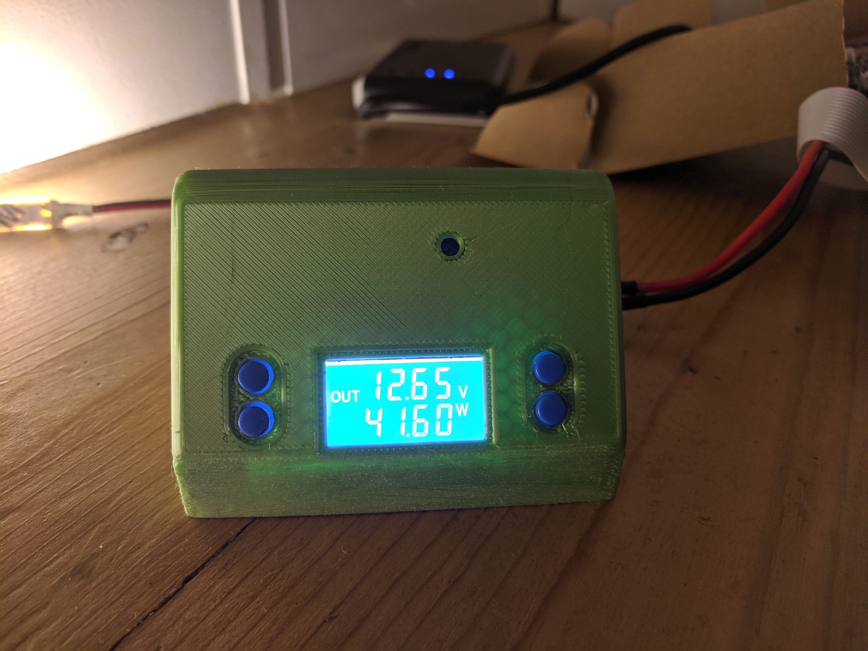
I think I found the worst way possible to test a load on my pack, I think the fact that I was making contact with the bulb pins directly on the xt60 connector I was causing some spikes. I think the DIYBMS is sensitive to this kind of spikes. Now I’m using my DC to DC adjustable power supply to power an LED strip and is doing this for the last 5 minutes just fine for the DIYBMS.
Inrush? The initial (inrush) current for a tungsten filament lamp can be between 10 & 15 times the normal running current, typically it is 12 - 13 times. So you could easily draw 5 A at the instant you make the connection.
5A will not be a problem for the batteries, but I think the fact that the bulb was getting crazy hot really fast and dropping it I was causing some spikes for the DIYBMS modules.
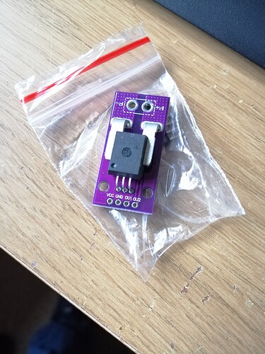
Stuart can you implement a monitor function for the current using an ACS758? ( hall current sensor - up to 200A, the 50A version is just 2.65£ on eBay )
You already have a voltage reference for an accurate reading on the modules and the extension port (sensor1), not to be for the each cell but at least one for the all pack.
@marius_r you must have read my mind
Stuart I’m glad that you are already thinking at this, will be a really useful feature. Hope to see it soon implemented in the DIYBMS. You can do so many things with something like this, even to set a rule if the current is higher to trigger the relay and disconnect the pack acting as a protection, or to estimate for how long the pack will run. Like I said so many useful features that will add to the value of this great BMS.
You one is the ACS758LCB-100B?
Gelisob. Thanks loads for this "How to program the BMS. It worked. Now I’m just waiting for the wemos to arrive from what appears to be the other end of the solar system to arrive.
But 1st BMS card built and flashes correctly when programmed.
I assume one that’s done, I can connect a battery to it and it should flash some how?
Connecting a battery you will get one short flash from the green led and that’s all, after that flash no activity from the modules at least nothing visual from the led’s.
Cheers. That exactly what I had. I guess it’s built right. Good news. I guess I’ll build up the rest while waiting for the wemos.
For a V4 board it should flash the green led every 8 seconds when in standalone mode (ie. no controller)
