I’m not an expert but you do need high and low voltage disconnect.
Low Amperage installation can get away with mosfets (aka solid-state relays) higher (+50A) are better off to use contactors.
As I have an hybrid, MPPT and inverter in one, there is not a separate line to the battery for charge and discharge.
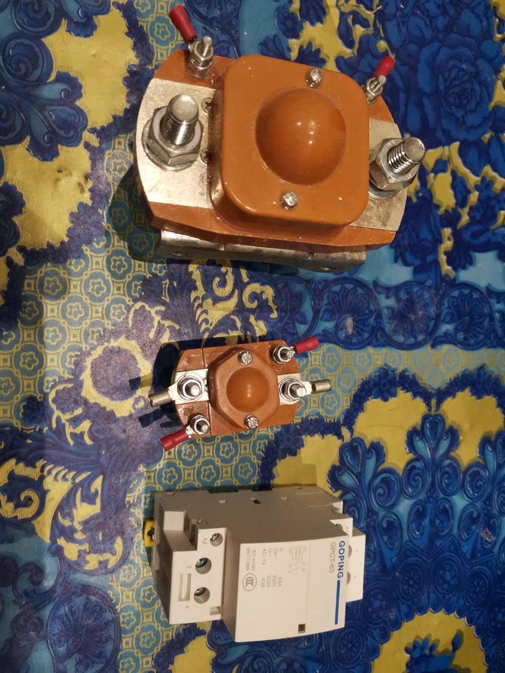
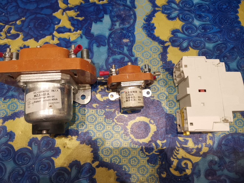
I use small contactor to stop the charge at the solar panels connection.
I use AC contactor for discharge
And a larger one to disconnect the battery when needed in absolute emergency.
That is 3 of the 4 relays used on the relay board at the controller.
I use the 4th for fans, if the cells (or cell PCB’s) ever get too hot.
That’s about it.
You need to control your power into the battery array for too high cell voltage.
You need to control your power out of the battery array for too low cell voltage.
The rest is (a welcome) extra.
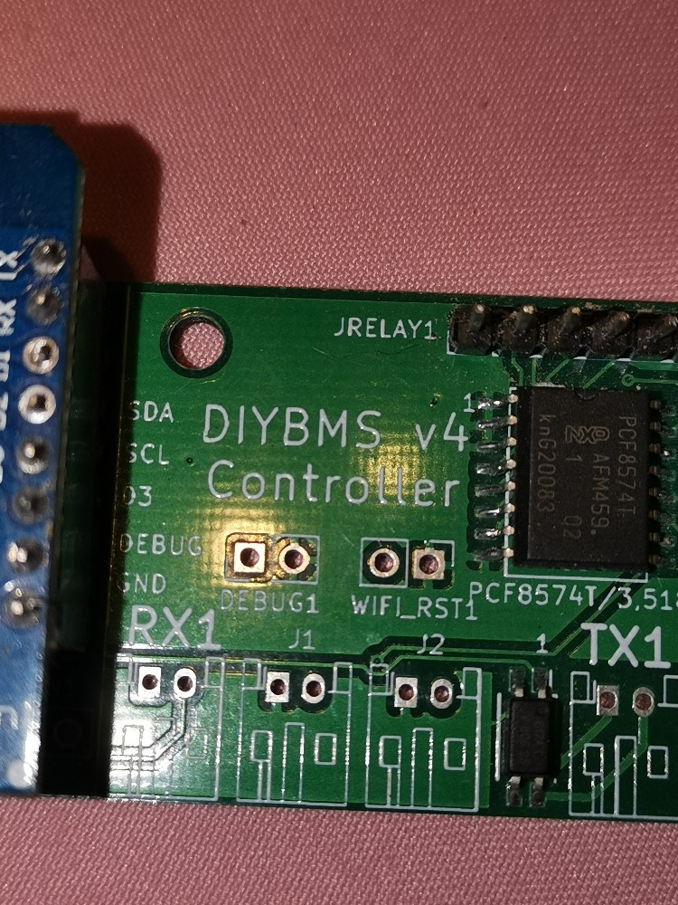
For the wemos, both standard “pro D1”(8mb) and clone (4mb) works with the software from Stuart.
If you can buy the pro, better to have enough space on the wemos if future software upgrade would need it.
Hi stuart
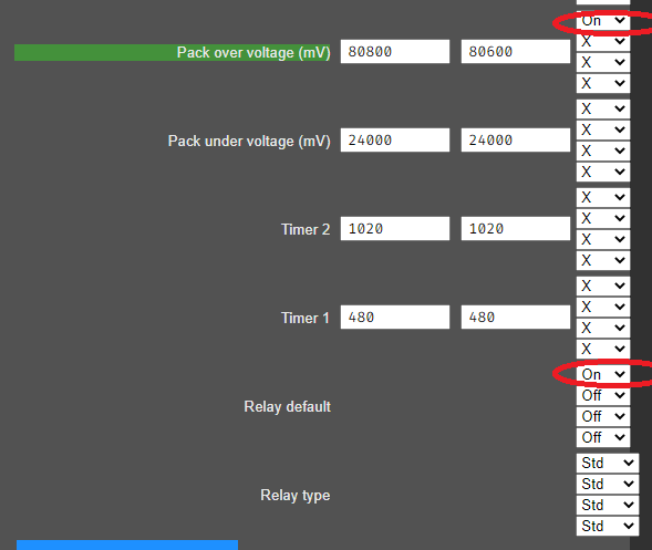
On the firmware with hysteresis (although the wizard is the same), the settings logic is not clear. Relay default - It is logical to assume what state to keep the relay in before any logic rule is triggered (if enabled, then it is logical that the level is high and vice versa).
Pack over voltage (mV) - It is logical to assume that when the enable value is reached, switch the output to the state indicated in the corresponding field opposite and vice versa.
However, in practice, everything works the other way around.
To add to @rolfbartels question to you, “Normal” refers to the state of the relay contacts with no voltage applied to the coil.
That is not the same as the logic output, because it depends on how the coil is driven by the logic. A coil that is wired between the power rail and the logic output will be energised when the logic is LOW, and the NO contact will be closed. If the coil is wired between the logic output and ground, it will be energised when the logic is HIGH, and the NO contact will again be closed.
I see some confusion. In your image, On and On doesn’t necessarily mean ‘On’.
If this pack over voltage becomes True: then do this.
On means change the default relay state, not the relay is now on. If On means On, then there is no need for the default relay section.
The relay “ON” state the BMS refers to is the energizing of the relay. As others have said, if you use the “NC” connections then this will be inverted.
What the parameter is responsible for - Relay default? In my understanding, what state should the relay be in by default? I understand correctly that if I switch this parameter to on, then the logic output will be 1, if I turn it off, then 0? (Other parameters are disabled)
Correct. The “default” rule is the starting position of the relay when the BMS is powered up (after the code has started running). On=1=Energised, Off=0=Not Energised.
Wow. Maybe that’s the problem? I expect the output to change immediately after the setting is changed, and you say that only after a restart.
Or I misunderstood and this does not affect the level of the logical output?
You misunderstood, what I mean is when you first power on the controller the relays will be in an unknown state, after a few seconds the code will start and set the relays to the “default” state.
Once the code has then stabilised and read the modules it will run and process the rules, and then apply the relay state as the rules determine.