Well that sucks, I just mailed JLCPCB about the ATTINY841 and they say they have no plans to restock the ATTINY841-SSU as there have been to few orders for this part. So back to ordering separately.
Yes thats what the relay bank is for. Charging should be done from a specialist charger device/unit and will stop over charging itself - the BMS is there to “kill it” (via relay) if an error occurs.
If you just click “BUILD” instead of upload (under the env:esp8266_d1minipro options), the terminal window should show similar to the below messages. You want to see “SUCCESS”
Processing esp8266_d1minipro (platform: espressif8266; board: d1_mini_pro; framework: arduino)
--------------------------------------------------------------------------------------------------------------------------------------------------------------------------------------------------------------------------
Verbose mode can be enabled via `-v, --verbose` option
CONFIGURATION: https://docs.platformio.org/page/boards/espressif8266/d1_mini_pro.html
PLATFORM: Espressif 8266 2.6.0 > WeMos D1 mini Pro
HARDWARE: ESP8266 80MHz, 80KB RAM, 16MB Flash
PACKAGES:
 - framework-arduinoespressif8266 3.20702.0 (2.7.2)
Building in release mode
Retrieving maximum program size .pio\build\esp8266_d1minipro\firmware.elf
Checking size .pio\build\esp8266_d1minipro\firmware.elf
Advanced Memory Usage is available via "PlatformIO Home > Project Inspect"
RAM:   [=====     ]  45.3% (used 37144 bytes from 81920 bytes)
Flash: [====      ]  37.9% (used 395592 bytes from 1044464 bytes)
============================================================================================== [SUCCESS] Took 6.56 seconds ==============================================================================================

Environment        Status    Duration
-----------------  --------  ------------
esp8266_d1minipro  SUCCESS   00:00:06.563
wemos_d1_mini32    IGNORED
============================================================================================== 1 succeeded in 00:00:06.563 ==============================================================================================
This is probably a mistake at the outset - however ESP8266 doesn’t care which pins are used for i2c, it uses a software implementation so any pins can be used.
1 Like
What UART board ?
I’m using an esp01 uart programmer (hw305) , but besides that I have various boards, with and without an iscp port.
I got the controller board pinout by measuring them with a multimeter… So it’s an iscp port.
But I still can’t find any documentation on programming the attiny without a uart in platformio. I seem to understand that I have to change some variables like protocol to program instead of upload…
I know the cost of the uart board shown In Adam welsch’ video is only like 2 euro… So if I can’t get this figured I’ll just order one.
Please excuse the questions, this is like my second arduino project and it’s a steep learning process.
The controller board (ESP8266) is programmed directly from a USB cable - no additional programmer needed.
The ATTINY module boards are a standard 6 pin ISP header port.
my soldering skills improve rapidly.
quite happy with the end results.
just not sure if this optocoupler will work. (i could not find the right one on mouser or digi-key)
This one: VOS617A-X001T have, as far as my limited knowledge could make out from the specification sheets, the same specifications as the HMHA2801

I hope it works.
if not, i have the HMHA2801 on order via aliexpress, but that can take months to arrive it it does at all,
For the controller board I understand the RX1 and TX1 need for JST socket.
What is J1 & J2 used for?
J3, J4 & J5 are optional, but optional for??
C Sens1?
Wifi RST?
I’ve tried to find explanations for the options, could not find it…
C Sens1 could be a thermistor, but it have 3 holes…
Please explain it to me.
I always like options, mostly when I know where to use them for 
Same issue for me and the same fix, how come we all missed this step ?
Only tx1 and rx1 are needed. All the other sockets are optional inputs. J1 can be used for an emergency stop button if needed.
My just built V4 controller module doesn’t seem to go into access point mode and I never see the WiFi SSID to connect to. It appears to work with a battery module - I can see them talking to each other via the LEDs. When I reset the controller, the green LED goes on for three seconds, then off, and the blue LED on the WEMOS blinks occasionally. If I short Wifi_RST when the green LED is on, the LED stays on, but still no SSID on Wifi. I checked for the SSID on multiple devices.
This is the WEMOS module I’m using: https://www.amazon.com/gp/product/B07G9HZ5LM
Any suggestions? Thanks.
Rich
Are you using the code from platformio?
If you are using an android device to try and connect disable mobile data first.
Yes. Using platformio from Visual Studio on my mac. I tried the SSID from my android (with and without mobile data), and also my Mac, my MacBook, and my Linux laptop… Maybe I’ll try reading the debug serial output. I’m not sure how much flash my WEMOS board has. Does it matter?
I get the following when power it up without shorting wifi_rst:
SDK:2.2.2-dev(38a443e)/Core:2.7.3-3-g2843a5ac=20703003/lwIP:STABLE-2_1_2_RELEASE/glue:1.2-30-g92add50/BearSSL:5c771be
Apply default config
pcf8574 not fitted
Clear AP settings1
Setup Access Point
mode : sta(48:3f:da:4f:83:ad)
add if0
scandone
DIRECT-d9-HP M402 LaserJet
del if0
usl
mode : null
mode : softAP(4a:3f:da:4f:83:ad)
add if1
dhcp server start:(ip:192.168.4.1,mask:255.255.255.0,gw:192.168.4.1)
bcn 100
Access point IP address: 192.168.4.1
S:80/1/1=0 0 0 0 0 0 0 0 0 0 0 0 0 0 0 0  =925/Q:2
S:80/3/2=0 0 0 0 0 0 0 0 0 0 0 0 0 0 0 0  =7301/Q:1
If I short wifi_rst, I get nothing on debug serial and the green LED stays on, and no blue LED activity.
Rich
If I design a controller board from a schematic that takes SDA (pin D2, or GPIO4) and SCL (D1, or GPIO5) from the D1 Mini and wire them to the matching pins on the PCF8574; will it work using the code as it stands?


Thank you Stuart. Helpful as ever!!!
I indeed have mushroom emergency stop button.
J1 will course the relays to disconnect?
(I will have contactors on 2 of them, for charge and discharge)
I have an other question, it’s about the dump load.
Standard the small BMS PCB can do already 850mA.
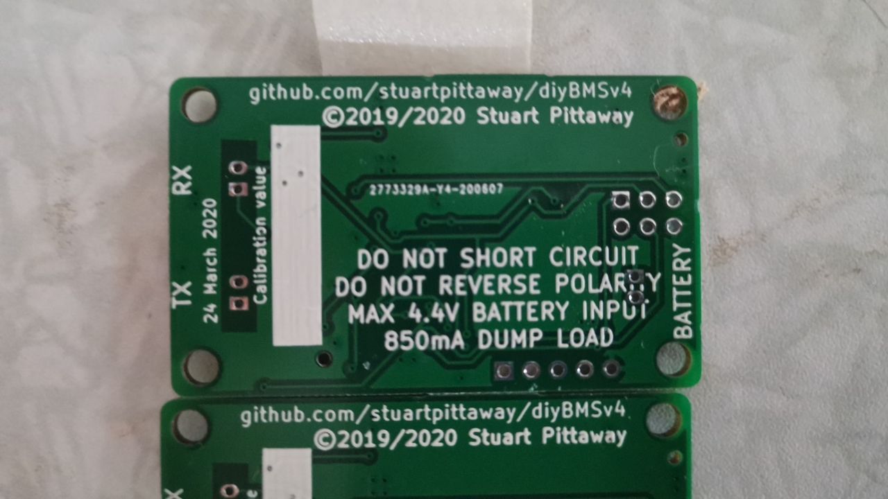
I remember reading about that cool block will increase this capacity.
I’m curious how much it can burn off with the dump load with small cool block and active cooling fan
Most BMS can do +/- 200mA, Daly BMS 35mA.
The 850mA is already a lot more then “competition”.
I didn’t have the pleasure yet of burning extra charge during top balance.
And have no idea how high this in theory can get.
With sunny weather at noon, I can charge Solar max 225-250A (S16) (43*330watt Poly plannels)
Not a problem for 1016Ah.
I just hope I never need to burn off this kind of charge 
Just blanked and reflashed my ESPController module with the latest code because I wanted to change my wireless settings. Although I can see the AP and connect to it, when I try to go to 192.168.4.1 it redirects to http://192.168.4.1/softap.htm and then I get a “This page isn’t working” message followed by “192.168.4.1 is currently unable to handle this request HTTP ERROR 500”. I have tried with and without mobile data connection but it makes no difference.
You didn’t run the “Upload File System Image” option in PlatformIO did you ?
It just triggers the rule - so the relays would do whatever you program them do to in that situation.