Thanks, living in South Africa makes it hard to get these components and shipping them in takse 4 months, I do have 5 controllers and 50 module on their way I ordered in March/April, was hoping to DHL something in 2 weeks to me as I still need to fix the R19 and R20 issue on the modules and solder the ATTINY which also has not arrived yet, but thanks.
1 Like
@stuart, I have new strange action of my BMSv.4. Internet down for 2 days and counting, dont know if this a contributor.
Think the controller is rebooting after one sweep. I get normal green light sweep, then controller appears to reboot, some random blue lights on modules, then normal sweep.
At present the controller expects the internet to exist - its possible that the NTP date/time is causing the controller to reboot if it doesn’t get a connection.
Can you see the output from the DEBUG pins using a serial cable?
Thanks for prototyping the mouse bites so quickly! If you’re willing to share the files, I’d like to order 20 “4-packs” along with 5 controller boards to replace my current BMS.
1 Like
I’m going to keep the files private for now until I know they work, don’t want you wasting money if there’s a problem
1 Like
Understood. Appreciate the due diligence!
1 Like
No wonder I was having trouble stuffing code into my controller!!! I was doing it the old fashioned way with the new code!
Having blown up 3 ATTINY841’s (I’m a doofus and hooked the USBASP the wrong way), I got my 4 cell monitors (and 3 pieces of PCB Art) and a controller up and running.
This is very easy to do thanks to stuarts video. I even did it on a mac (needed bootcamp for the wemos though, it hated me on mac os!). I’ve tested each module with the controller and a single 18650, and now I’ve twisted some wire pairs to make up interconnects for the move to 4S. Then once the glass fuses (2a) arrive, I’ll reprogram the controller for LFP from LiIon and move it to the LFP pack 
Note to everyone, make sure pin one on your 10 to 6 pin cable is actually pin 1 and not pin 6, lest you blow up the attiny, also twisting wires is easier with an electric screwdriver. I did it by hand and now I my right hand is cramping!
Thatks again Stuart. Terrific work!
1 Like
Good advice!
I have been trying to get my controller to work and was wondering if the problem i have with the communication might be down to the wemos d1 mini pro possability being a clone. Can anyone tell me if the clones work and how to tell if it a clone or not.
Also if someone could tell me were i can buy a genuine one in the UK without paying a arm and a leg.
I know Stuart has said he has got them from Aliexpress but dont really want to wait that long.
Hi Mike, it should work even with a clone. Did you follow my video for programming? What problems are you seeing?
Grüezi Stuart, maybe I’m not really seeing something properly here, but how can I charge / discharge this set-up with more than 1a?
Am I correct in assuming that I can safely charge and discharge this set-up, outside of the controller? If so how can I start or stop charge and discharge? Is that what the relay bank is for?
also , I cant seem to find a pin-out for the UART to module board, does anyone have any information on that ?
@stuart
No i didnt but just trying it now, i used the compiled code a few months ago but not had chance to have another look till now. The problem i was getting was none of the cells would populate and came up with unable to comunicate with modules from memory or something like that.
I tried each module one by one, doubled checked all my cables had no break in them were i joined them and they are twisted. I have doubled checked my soldering of the controller board and the cell modules were made up.
I will update you once i have tried out your programing video, thank you so much for your help.
Mike
@stuart
I am getting the following problem when i upload in platformio.
I doesnt finish the compile.
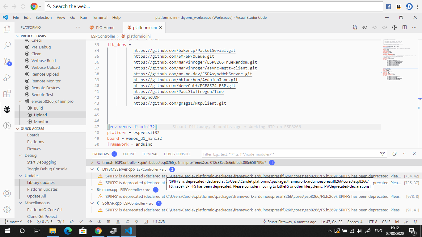
Many thanks
Mike
The SPIFF warning can be ignored. If there is an error it will be further down the page.
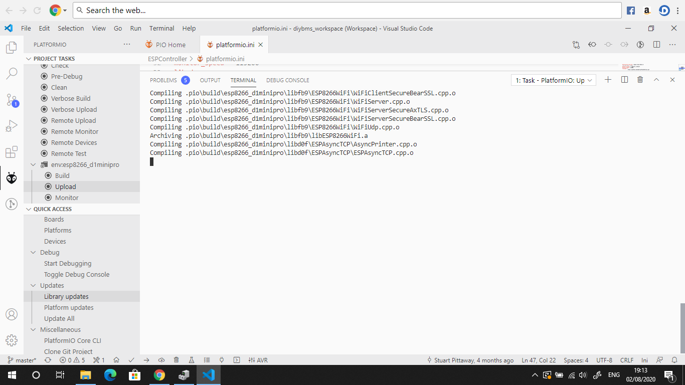
Hi Stuart
The compile doesn’t go any further than that for some strange reason. Doesn’t say completed.
Hi Stuart,
Is there a reason the SDA and SCL pins are reversed on the Controller schematic?
You’ve got SDA on D1 and SCL on D2.
Thank you a lot Stuart. For me it will be much easier, because ordering 100 modules with one order is now possible (the max of 30 pieces with soldered parts on it). I will try to install KICAD and do a ‘mousbite’ design on myself for a “4 in a row” module and connect the TX-RX of neighbour boards. Maybe this is possible. Our BUiliduing Blocks are 4S batteries connected to 16S Strings, so we can do an easier, faster building.
Edit: And Stuart, if your “mousbites” are not to break apart, a Dremel will do the job.
Check if Wemos D1 is complete in the socket. I had some vibrations on transport and it pulled some millimeters out and had the same symptoms
Have you seen the leaf battery design, this already has 2 BMS modules on 1 PCB?