DIYBMS v4

Has anybody attempted to connect two controllers to a single CerboGX via CAN? Not after DVCC. Just would like LVC/HVC via CAN and to see basic bank/cell stats from within the Victron environment

how to program the v4.5 module? i have the programmer for the shunt but where to download the file for the module?

In the releases…

https://github.com/stuartpittaway/diyBMSv4ESP32/releases/tag/Tag-2023-02-21-08-55

Download the ZIP file Compiled_Firmware_2023-02-21-08-55.zip

Inside that Modules/Hex and the files are there.

image

1 Like

What module fimware corresponding with firmware ESP32 in this release?
https://github.com/stuartpittaway/diyBMSv4ESP32/releases/download/Tag-2023-02-21-08-55/Compiled_Firmware_2023-02-21-08-55.zip
i have v4.40 cells boards, now with esp8266 controller. Exist 3 variants on this release…
Please publish schema UPDI interface to esp controller, published is only board for programing…

They often have a soldered jumper allowing you to replace the jumper with a relay for S/W control.
It’s the RUN jumper in my case:

@stuart

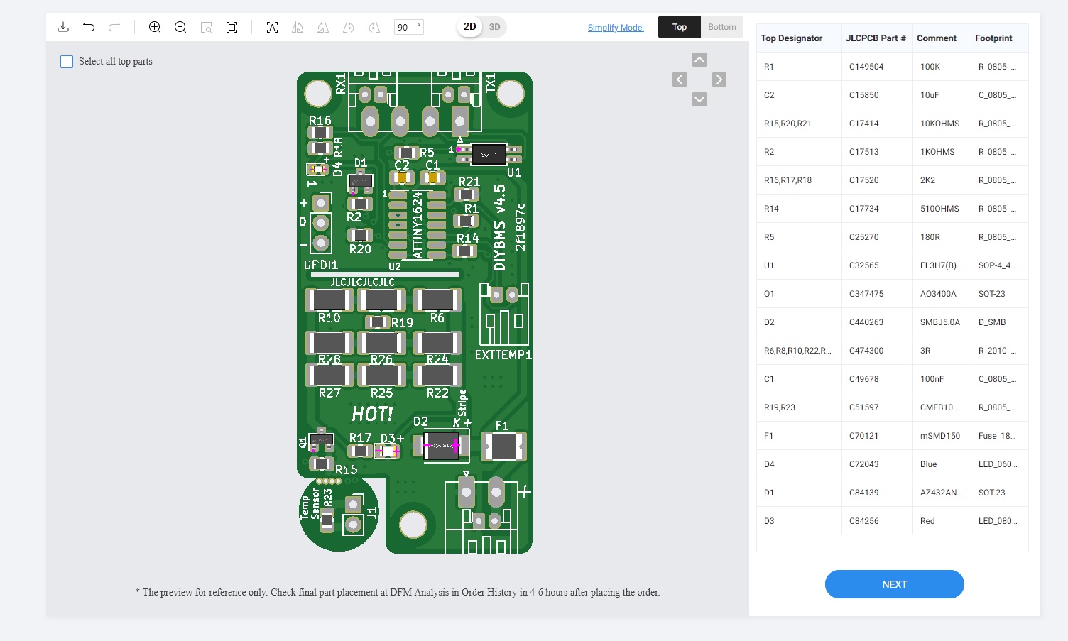
does jlc place D2 wrong again?

yes, d2 is in wrong position. White stripe on diode marked cathode. Diode is in zener mode (reverse polarity), its no normal diode…

Yes, probably. I’ve given up trying to correct them on that part, they keep swapping the pin orientation around. It’s a TVs diode and they don’t appear to understand.

@stuart @Smurfix
the dynamic charging algorithm is working very well

i have a offgrid system with sma sunny island, sunny boy and victron charge controller

here some graphs from the victron vrm

3 Likes

Glad to be of service. My battery is quite happy about it too.

1 Like

Thanks for the feedback @voltmeter and @Smurfix for sharing the logic!

Stuart, I have been using the diyBMSv400 for over an year and suddenly one module started behaving strangely. It kept bypassing till the battery was fully drained.

I removed the same from the pack and saw the voltage was being read incorrectly 4.4V causing it to bypass.

The voltage divider part is working- I added a resistor in parallel to the lower part and the voltage is dipping as expected. The upper half of the voltage divider was not showing any change with the addition of the parallel resistor.

The reference diode is also working. I ran it off a DC power supply and it’s holding steady at 2V.

My suspicions are the following -
AREF pin could be faulty
PA7/ ENABLE pin could be faulty

Have you faced any similar issues
Could you please let me know the debugging steps.

My pack is a 13s 5p, Controller is based on ESP8266.

Really appreciate and respect your valuable contribution to the Community.

Hi @Ashin_John. I’ve not seen any reports of hardware failure like you describe - it could be a number of things such as you mention. Might be worth checking for foreign objects on the board, bad solder joint?

I did see similar behaviour once when the ATTINY lost its flash memory configuration - so check that first in the web interface (check the calibration value isn’t zero). Additionally, it might be worth re-flashing all the cell modules using a newer version of the module code, to see if that helps.

Hello
It might be the wrong place here to ask - sorry for that.

I’m wondering if the DIYbms is ‘just’ a balancer or if the main (charge - discharge) current is switched off in case of reaching e.g. ‘Cell Discharging Cut-off-V’

I looked through the schematics, but on controller board I only see 2 solid state relais AQY282SX.
AQY282SX is for 500mA, so I think they are not for this purpose.
Or do I have to use an external relais?
Or, the most likely, I did not understand everything in the right way.
Please give me a short advice.
Thank you!

Diybms is designed to control external chargers over CANBUS (like Victron or pylontech).

It can also use it’s relays to drive other safety devices like contactors or bistable relays to protect battery packs.

This is similar to the batrium range of products.

1 Like

That’s the missing link! Thank you!

Well, you still should have an external relais. This is essential for safety. You do not want to risk your system to go belly-up due to some random misconfiguration.

However, this relais should only trip if the rest of the system misbehaves in some fundamental way – and blatantly ignores the voltages or currents which the BMS tells it are acceptable. High-energy batteries are not “battery full? well, turn off the charge path” devices.

In particular, when you’re charging you have multiple kW going to the battery. If you trip the relay, all that power needs to go somewhere until the rest of the system can react. The resulting voltage spike may or may not fry something.

1 Like

@stuart we try to place an order for the controller board v4.5 and got some questions regarding the ordering:

  1. it seems like, that JLCPCB is showing the parts orientation completely wrong. i guess they are going to correct that during their order review, correct?
  2. on your github it seems, that the bom file in the export folder and the page “diyBMSv4/ComponentListBOM.md at master · stuartpittaway/diyBMSv4 · GitHub” do not correspond to each other. Quick example: C8 and C9 are listed in the ““Do not place” items” section. When I look those parts up in the drawing, the are required for CAN-bus. similar issues can be found for D7, R26 und R7.

the collective order takes place here, if someone would like to join in:

1 Like

have you tested your boards now?

I have the old version for 4.4 boards running on my system, but for the new boards I still lack the attiny 1624 and therefore they have not been tested yet

1 Like