I should have written - need to reduce the power going into the cells.
How the voltage or current is controlled, really depends on the installed hardware - as you mention Victron only permits voltage control, as that fits their purpose/design.
@Smurfix I know you’ve explored this option in some detail in a previous post, but can we explore this again, as its logic I’d like to bake into diybms.
Following the logic of voltage controlled charging would you expect to be regularly recalculating the charge voltage, or just as a cell approaches the maximum permitted per-cell voltage (3.5V for example)?
In the example above, (assuming 16 cells) you have 15x3.4V + 1x3.5V cells = 54.5V (actual cell voltages), are you then recommending a charge voltage of 54.6V (0.1V higher) to allow the 3.4V cells to “increase 0.1V” ?
Well, of course this calculating exercise matters more, the further your top cell is from the linear region of the charge curve. If all your cells are at less than 3.4V, the voltage you pass to the charger won’t matter because it won’t get there: the current limit will hit first.
The CPU time to do this isn’t much compared to all the chatting with the battery and the charger/inverter etc., so I’d just run the algorithm every time you get new cell voltages.
Well, in this example I’m using 54.6V to allow the one 3.5V cell to go up by 0.1V because, you know, that’s exactly what’s going to happen when you continue charging. If there were two cells at 3.5 I’d allow a charge voltage of 54.7V. I’d expect the 3.4 cells to essentially not change at all in this situation.
In my BMS code I’m using the following algorithm:
Let’s say the max voltage per cell we’d like to allow is M (3.6V or whatever), the highest cell voltage in our stack right now is H, and the voltage where the charge curve stops being linear is F (=3.4V or so, for LiFePo4). Set U=1 (but see below).
If H >= M, tell the system to stop charging. Return sum(min(M,C)) where C is the voltage of each cell.
Calculate a voltage range R as min((M-H)*U, (M-F)/3).
Calculate S as the sum of the current voltages of all cells.
For each cell whose voltage C is at least H-R, add ((M-H) * (C - (H-R)) / R) to S.
Return S as the maximum charge voltage.
Thus, if you have a max voltage of 3.6 and your top cell has 3.5V, this algorithm adds 0.1V (for the top cell). If you have another four cells with 3.45V while everything else is at 3.4, you get another 0.1V: the further away a cell is from the top, the smaller its contribution to the allowed max voltage is going to be.
The idea behind the min(…, (M-F)/3) limiter (which I have ignored in the preceding paragraph, to simplify the numbers) is that when the cell voltage is in the flat part of the charge curve every cell behaves differently. Charge three cells which are at 3.37, 3.38 and 3.39V, in series, and it’s anybody’s guess which of these will head off to 3.5+V space first while the other two voltages don’t change (at least not enough to matter). As an example, if M=3.6 and H=3.48 this ignores everything below 3.44V instead of 3.36V.
This keeps max voltage low enough so that even if the BMS stops responding and the Victron-or-whatever system doesn’t notice, we probably won’t overcharge any cell, while not lowering it so much that you can’t charge with 100+A any more: doing that raises the system voltage at the charger side, due to battery/cabling/etc. resistance.
Another element you might want to play with is the factor U. If you have non-uniform cells in a stack (e.g. you know that some have been over- or undercharged in the past) you might want to reduce it somewhat. On the other hand, I expect LiIon cells with their steeper, more-uniform charge curve to support U=1.5 or thereabouts, though I don’t have any and thus didn’t test that yet.
You also want to set the max charge current dynamically. e.g. I_CH = min((M-H)*I_CH_MAX * 5, I_CH_MAX). I_CH should not be allowed to rise too quickly because the cells’ internal resistance causes cell voltages to rise with the current and you don’t want the whole system to oscillate; I’m using N=(M-H)*I_CH_MAX * 5; if I_CH>N then I_CH=N else I_CH=min(I_CH_MAX, I_CH+(N-I_CH)*0.1).
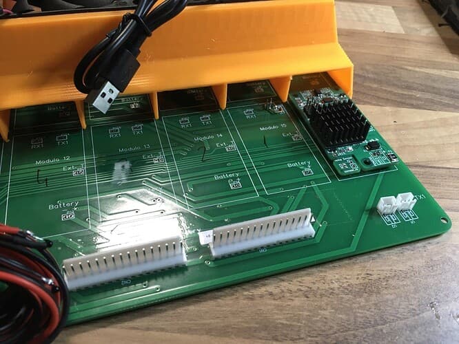
Yes, I have the same problem, but it didn’t even occur to me that it could be a problem with the board, I also have them at 5K. The speed is enough because I will not pass in the best of cases 48 modules (now 36) do you think that this speed limitation is a consequence of the design of the board? I could revise the layout to increase the thickness of the data tracks a bit, but I’m not sure there’s room.
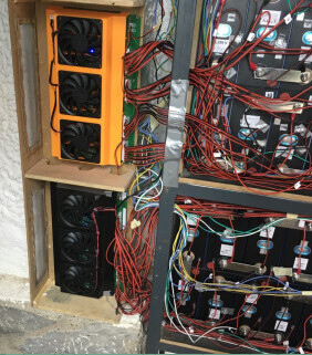
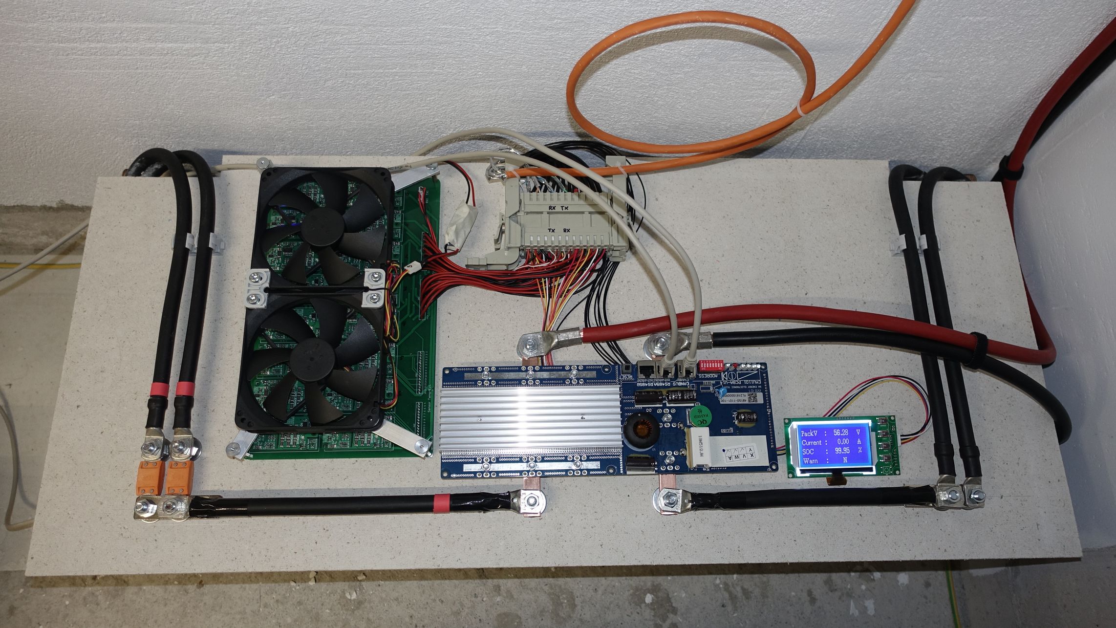
I love how your setup looks, is the other BMS a Seplos? Do they work simultaneously? no interference? At the time I tried to combine DIYBMS with a capacitor BMS and the result was not good.
I have done a small (cough) rewrite of the communication protocol that speeds up the whole thing a lot, despite the low baud rate. Smaller header, variable-length packets, concurrent send and receive.
If somebody wants to integrate these changes into the diyBMS controller code, I’m happy to help; I do have provisional patches. Problem is, the controller code I’m using on my own systems is written in MicroPython …
i think the 9600 com problem is because the data track on the board is to close to each other so normaly you twist the com wires to avoid problems
maybe it will be better to use through hole contact and solder twisted wire for the communication so you have more room for current tracks and temperature sensors.
or place the com tracks as short as possible on the board in 5mm distance to each other and the longer ones make through hole for cable soldering
maybe it will solve that problem
the seplos works fine with the diy bms.
the seplos is a backup if somthing is going wrong with the diy bms so the seplos do the disconnect the diy bms do the balancing because the seplos can only balance with 150ma
and the diy bms is to slow even with 9600com on 32 modules i have now 16 but will use another 16 in future
so the seplos disconnect really fast
i have peak charge power of 10kw on a 23kwh battery now, another 23kwh is in costruction
That may be one of the issues, but the major factor if the optoisolator switching speed - its not a “digital comms” isolator (which are generally more expensive) so only supports switching speed.
I’ve got mine running at 10,000baud without comms issues, but it really does depend on how the cables are run and what EMI is picked up from other electronics - especially when high power charge/discharge is going on.
10,000baud is the max I can get out of the standard isolators and to be fair, there isn’t really a need to go quicker, unless you have hundreds of cells.
Would be interested to take a look, I also started down the route of variable-length packets as that will save quite a bit of time, but felt like an over optimisation for most people who are using 8-16 modules, so I spent my time doing other changes/fixes.
NB: I also removed the floating-point code from the cells. Doing math is the controller’s job IMHO. The fact that even with the comms enhancement there’s now 1k of free space in the cells’ flash to play with / add debug code to doesn’t hurt either.
even with 10k it is to slow for me with 32 modules the voltage rises so fast at the end on lifepo it need a update maximum in one second
thats why im charging only to 3,5v to have a safety margin to 3,65v disconnect.
the seplos bms does a lightning fast disconnect while the diy bms is still updating…
Ok, in the next few days I’ll take a look at the interesting work @Smurfix has done and see how best to integrate some of those changes into the controller to control the charging voltage.