Hi everybody,
First startup of DIYbms v4.4 and esp32 controller here. I have combed thru this thread and tried many tips but to no avail. Should there maybe be a “First start problems”-sticky in the conversations?
Everything went fine installing but the controller gets stuck on “Stabilizing”-screen and “waiting for modules to respond” on top of the web interface. A green blinks on the controller, slow & random blue blinks on one module and two quick blinks on the other. Seems repeating.
Modules tab says NaN. Settings tab I modified to 2S1P (for my test setup).
I programmed the modules with a cable from the controller without errors (latest firmw). Also upload to esp32 without problems (also latest, used pyFlasher).
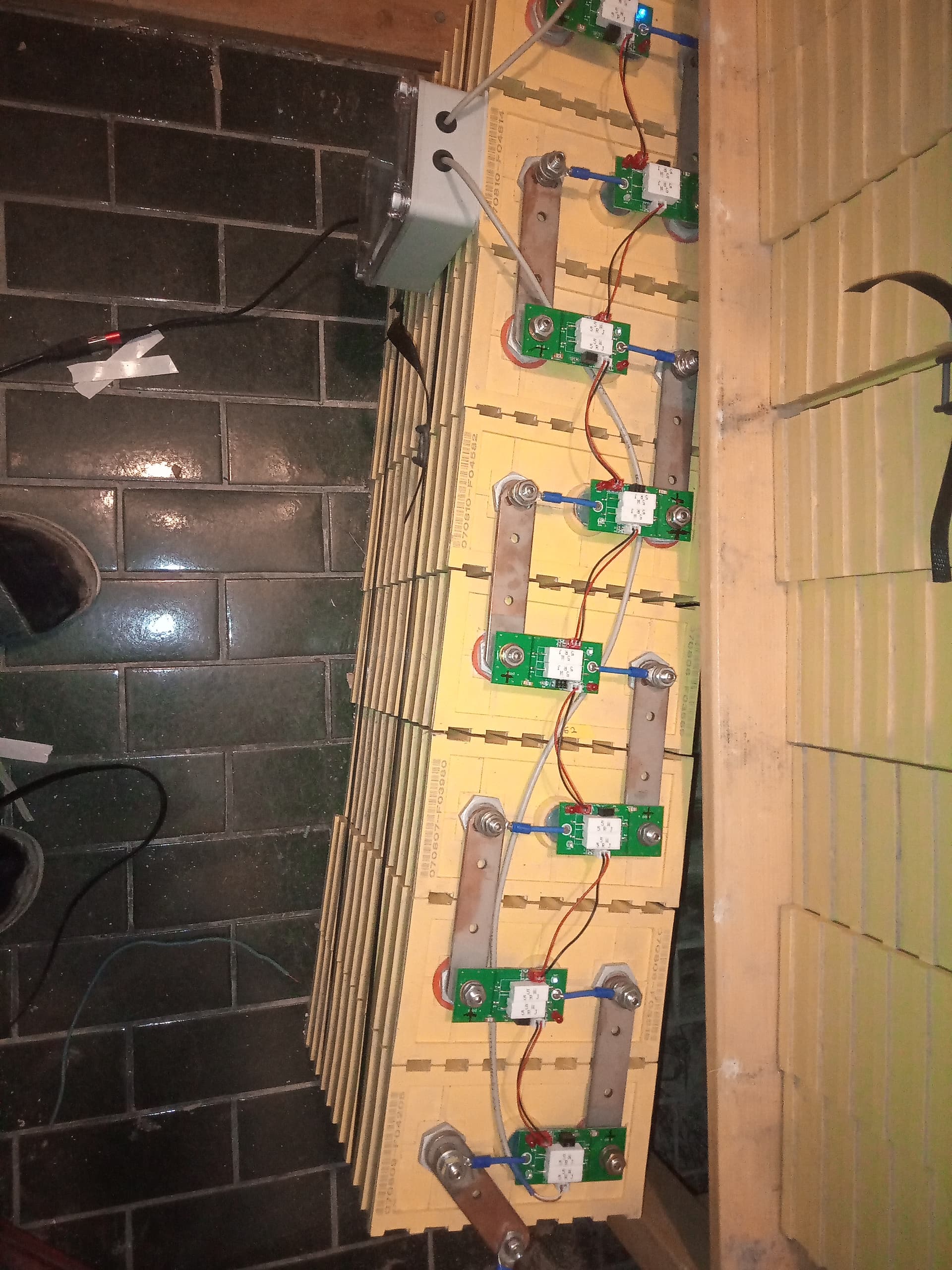
Two pictures of my setup if someone spots a problem. I checked some of the diodes etc for misplacement but cant figure it out.
EDIT: I uploaded the “boardtest” with NodeMCU pyFlasher. It beeps but does nothing else.
Help please, I just don’t know where to start troubleshooting.
It looks like your TX is connected to TX.
Flip the Module upside down to see the correct TX/RX ports.
The front of board says RX above the TX connector.
Yep, the Ignored counter keeps going up.
Double checked TX2RX-wiring. Not crossed.
I made some progress: I tested the modules one by one. The module with the corner broken off for extra length doesn’t work. the “untampered” one does give proper readings.
So one bad apple soils the whole thing?
want to test and hopefully help the Victron CANbus integration.
I checked a bit more the pcb routing (haven’t tried to look at the code yet!) and it seems to me that setting up a board with the ESP32 (no screen, don’t need it), no TCA and SN65 chips onboard and a CAN chip system should be able to read the input from the cells and sent can messages on the bus to the victron venusOS. I understand no relays will work (don’t care for my testing!).
am I missing something?
repeat, just for testing, don’t even have the cells here yet!
Hi @stuart ,
I have found out why it was such a mess with temperatures. The problem was with sensors, it looks like I have damaged them by snapping them off. So, they must not be snapped off and must only be cut off, otherwise thermistors could be damaged and show some nonsense.
Another thing, is communication problems. Maybe you can give some advice.
At the moment I have 2 banks. 1 was working fine and stable. After I have added another one - the amount of errors was significantly high. Since redoing cables doesn’t helped much, for tests I have put the 2nd bank on a spare controller, so every bank runs on a separate controller. Also all modules and controllers were updated to the same code version.
Bank 1 (“old” one, v421 module boards) alone works fine, 3 days of testing - no errors. The battery bank was in operation with currents up to 100A charging/discharging.
Bank 2 (“new” one, v440 module boards) at the beginning of the test there were some errors, but after resoldering ATTINY chips on a couple of boards - no errors more for 3 days. The battery bank was NOT in operation, the test were done “on the table”.
Since for 3 days all was ok, I have put both bank in operation and connected to the same controller in 14s 2p configuration.
Overnight there were 6 o.o.s errors between 2 modules in the “old” battery bank, where before everything was fine. I have changer the communication cable between modules with different “Packets received” - no result, now it is 9 by o.o.s errors.
Any idea why it behaves so strange: by 2 battery banks give errors in the place, where there were no faults previously, when it was only 1 battery bank?
Many thanks in advance
Update: in the evening it is already 50 o.o.s and 2 crc errors; package received difference between modules from screen shoot = 46, bad package count by all 28 modules = 2
Hi,
I’m fairly new to this diybms topic. But I have some questions for somebody more legitimate than me.
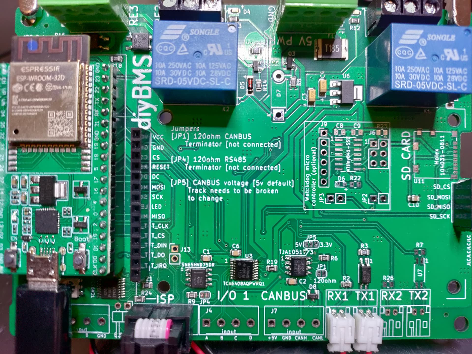
I have a problem with availability of few chips for eps32 controller.
So my question is, can I replace those with IC in brackets?
SN65HVD75DR (SN65HVD1782)
TCA6408APWR (not found)
TCA9534A (not found)
TJA1057GT/3 (TJA1050/c)
Both chips are 3.3V compatible and seems like a good replacement to me.
M´I right that those TCA chips aren’t essential for controller to work? So if I bypass them in software, will the controller work properly? (with some caveats, ofc) Or does anybody have a reliable seller on AliExpress for those? Can’t find it locally… (available in more than 30 weeks )
At first I have also thought that was a problem, so I cleaned the “snap-off” place with a file, checked the traces, but the readings from those sensors were still chaotic. I have checked the resistance then (directly on the thermistor) - it was a complete mess. But on newly built sensors, which were not snapped off but cut off, everything was fine. So I assume by snapping them off with pliers (as I have done at the beginning) there is a big chance to damage the thermistor mechanically.
This is not a direct swap unfortunately. The original part has a split voltage configuration where the IO side is 3v3 and CAN side is 5v (default). If you do not plan on using the CAN interface you can safely omit this component until you are able to source them.
Similar for this one, if you are not using the RS485 interface you can omit it. The RS485 interface is used for the Shunt so you may need it for that.
checked the specs, look identical to most seemingly important bits - to my understanding it wont suffer from what @atanisoft explains above as it’s 3V3 both for the I2C and output sides.
Slightly worried (OK, two euro worried tbh…) that the former has a Fast Mode I2C at 400kHz which the DIP version is missing. Wonder if @stuart design employs this fast mode or I would be OK without.
Struggling to find PDIP compatible to TCA6408A though. This does suffer the 3V3 IO and 5V control issue though.
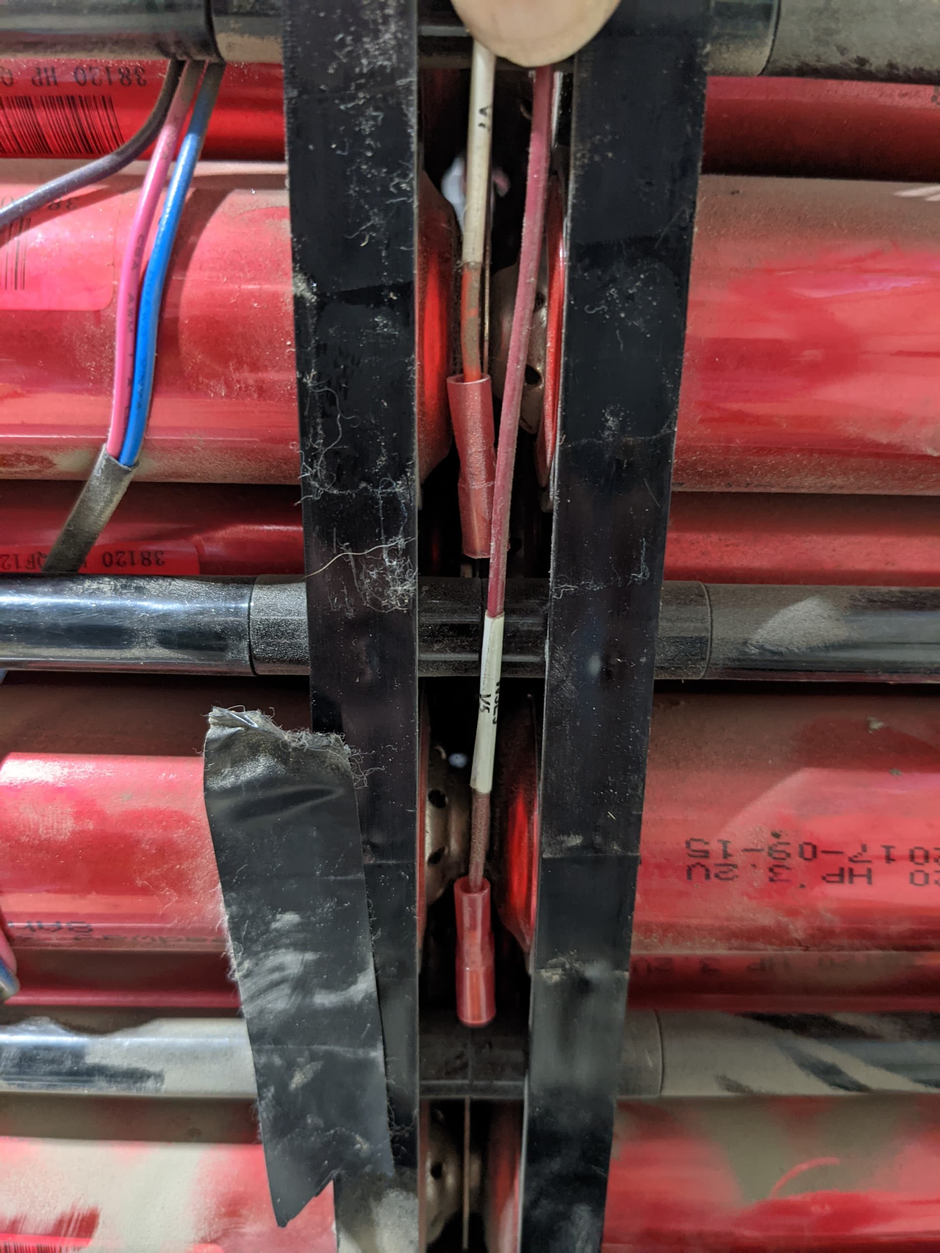
Ok so getting there much closer now and have test setup running on 1 of my banks. The main issue i have is that the leads coming out of the battery module are all the shared wire for balancing so only 9 wires for 8s pack.
I am seeing the voltages wildly swing as hinted that they would when the cell next is being balanced. Is there any way to reduce this without having to pull my modules apart as it will be a total pain to break the modules down to then rebuild back with the extra wire and the existing connectors that are in place dont have the spare pins.
This is the module made up of 48 Headway 38120 cells in 4p 8s all in a nice single contained module. On the wiring loom there are 3 Temp sensors, fan controls and an existing shunt for monitoring.
Ceramic resistors is good for an old or deep unbalanced battery. Good and balanced battery uses not much energy to balance and so ceramic resistors is overprice.
Do not see a pinheader for programming. Is it under the PCB? My opinion, you should connect modules to a bus bars instead battery screws. It would be simpler to remove faulty module without load shutdown.
Consider to make shorter cables to and from controller, decrease in likelihood communication errors.
So follow up with my question about needing the 2 wires per cell. Would having 2 wires going in to a single crimped connector be ok? So in this case i have a single flag connector for the BMS connection could i just replace it and put the 2nd wire in there for each of the connections?
The problem of common wires has been widely described, the increase in resistance in one of them due to the discharge of a module, modifies the reliability of the reading of the next module, initiating a reaction in cascade.
Today the only possible solution is that the wires that go from module to battery do not share cables.
I’m not sure but this problem in Batrium I think they solve it with a different approach to sampling, but it gives me that the creator Stuart, is focused on other more powerful developments and with more functionalities than to consider changing the firm so that it can work with thread shared.
My recommendation, he adds the threads you need so you don’t have to share them.
That is not quite true. The resistance might change by a tiny amount due to the temperature rising due to the additional current (the heating is due to I²R losses in the wire), but the main reason is the increase/change in voltage drop due to the additional current.


 )
)