DIYBMS v4 Shunt Design and discussion

@John_Taves I found that downloading the entire parts list from JLCPCB and putting it on a Google Sheets/Excel was really useful as you can then use that to filter on value/size etc.

Link for XLS download is here
https://jlcpcb.com/componentSearch/uploadComponentInfo

Hi John, the circuit looks good. Is the external temperature sensor working for you (connected to A0) I was under the impression that the maximum voltage for that ADC port was 1V.

Does the WeMOS have protection on it already?

How are you finding the solid state relays? On my post on the main forum topic you can see the controller board I’ve been working on.

Unfortunately, I’ve run out of pins on it and all the connections are using SPI bus so I don’t have any i2c on the board at all - which would make it a problem for using the INA chips. I could drop or make optional in some way the CAN bus or the second TX/RX module port.

For the display is it a parallel connected one? If so, you might want to consider an SPI connected one as it should require only two CS pins (one for the display and one for the touch controller) and the MISO/MOSI/CLK pins.

You might also consider the ESP32-S2 which has more IO pins than the DevKit-C or PICO. There are differences in the chip (single core, two UARTs, native USB/CDC). Support in PIO is problematic due to PIO not supporting upstream ā€œdevā€ releases (s2 support is only on esp-idf master and arduino-esp32 esp32s2 branch).

No its running off the SPI bus - actually I’m using both SPI interfaces on the ESP32. One controls the display (running at a high clock freq) and the other is for everything else running at lower freq.

It won’t be too difficult to have a dual purpose interface - most people won’t be using two module strings/chains.

I’m waiting for the DIN case to arrive so I can properly measure the internal dimensions and sort out the component placement and screw holes etc.

I’m using SnapTrack for mounting most of my boards and a board height around 81-82mm will fit snugly into this rail. I’d suggest something similar for mounting of the controller, shunt, etc.

What other devices are using SPI? Do you really need two bus speeds? If you are using SPI for CAN or RS485, you can switch to a basic transceiver since the ESP32 has built-in support controller support for both of these.

Using the display on 40Mhz SPI is really nice - very responsive no lag, just shows how powerful the ESP32 really is.

The remaining stuff is:

  • ISP programmer
  • SD Card
  • Touch screen interface
  • MCP23S17 (SPI I/O interface)

On top of that,

2 pins for module serial 1
2 pins for module serial 2
3 pins for module RS485 (including enable)
3 pins for module CANBUS (including enable)
1 pin for AVR programmer reset pin

I’m using 19 I/O pins!

Yeah, it is a very capable device for sure!

These should all use the same MOSI/MISO/CLK pins so they should only need a CS pin. For the SD card, be sure you are using 1-line mode. I’d also recommend using MISO:2, MOSI:15, CLK:14, CS:13 for the SD.

For the CAN connection you might be able to drop the enable pin, which transceiver are you using and how are you powering it?

For the AVR reset, you might be able to overlap usage with another pin (ie: gpio 0).

Also note that PICO D4 does not have GPIO 16 available. I’ve collected some notes on pin availability/usage here.

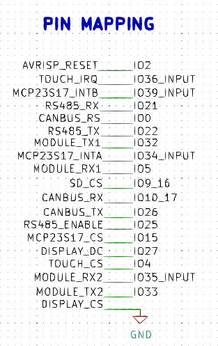
This is approximately what pin mappings I’m looking to use at the moment. I’m using the recommended pins for HSPI and VSPI (to avoid slow down via the multiplexor)

RS485 is using SN65HVD75DR and CANBUS SN65HVD230DR.

The PICO seems to have 2 extra pins available that the DEVKIT doesn’t (pins 37/38). I’ve also tried to make use of the input only pins where possible for RX lines etc.

image

These two pins typically have a filtering cap on them to 36/39. I wouldn’t use them for any purpose.

From the pin mapping you have provided it would appear that you might be using some reserved IO pins. GPIO 6-11 CAN NOT be safely used as they are directly connected to the onboard flash on all esp32 variants (esp32s2 uses a different range and are not exposed for usage). Also note that GPIO 16 should be avoided as it is used for PSRAM on some PICO-D4 boards.

Sticking to input only pins for RX is not a bad thing, there are only four of them to contend with (34, 35, 36, 39). The pins I recommended for SPI/SD are HSPI pins and are the defaults used by ESP-IDF for SD 1-line mode, arduino-esp32 SD library would use the same when using HSPI (default).

I assume you are saying that because my situation is so common, people won’t turn to DIYBMS to handle it. This is a good point. However my thinking is that it won’t be too much effort to make DIYBMS competitive with off the self solutions. This is why I asked Stuart what his goals were?

(If you are assuming my situation is uncommon: I have an RV. This is very common and has essentially the same needs as any off grid home. A single battery bank, solar panels, and an inverter. In both cases the user will want to know the state of charge, and the PV current is nice to have. Also the thing is rather useless without the relays.)

My take is that boards are cheap and that is totally irrelevant because the other costs overwhelm that. Shipping eats a bunch of the cost. The soldering is not cheap for those that don’t have a soldering iron. The surface mount soldering might be no problem, but I am avoiding it. The attiny progamming board needs to be purchased. Making the jst wires is a pain and securing the different boards is a royal pain. All of that affects the cost. When I see some text mentioning how cheap the parts are, I roll my eyes.

So my opinion if the goal was to have just one controller board, why not one like this? The 2x INA226 chips are a whopping $1.30 each, and the 3x TLC226 opto relays don’t have to be installed. In other words, so what if some users don’t want the current measurement and relays? This design can function identically to the current controller board, and it can measure current and also has 6x relays.

But, I see no point in just one option for the controller board. The Leaf module boards are an excellent example. I am going to make a single board that has 8x modules and the controller. This will eliminate all the daisy chain wiring and make it so that I only have to mount one board. Why not have a release that has 4x modules for a 12v system?

In order to reduce dumb questions the project has to be obvious. I found the jlcpcbassembly branch not obvious at all. I managed to figure out how to order the stuff, but later found the videos on how to do the ordering. My impression is that the videos are no small production matter.

If the idea of more than one controller option and the controller/module combo is reasonable, then I would organize the folders like so:
Controllers
Modules
ControllerModuleCombos

Under each of those top level folders there would be additional folders for the different variants.
Thanks!

I have not received this variant. The one that is currently working does not have the temp sensor thing and it has only 2 relay chips (4 total opto relays). I thought I paid attention to the ADC voltage range. You are making me nervous, especially since I choose a dinky smt resistor. Ugh.

You mean if I put too much voltage on the ADC? I’d have to review.

Are you asking about the opto relays (TLC226A-2)? My current board seems to be working fine. I have hooked up only 3. The DC/DC and the PV relays are both tiny amps, so the TLC226 is overkill. The inverter runs it’s LED display through the switch, so it draws over 100mA, and it works just fine too.

It makes no sense to me to NOT include the INA226 (as Mike points out the INA229 will handle 48v pack and one would hand solder that onto the same pins as the INA226). The INA226 has been available on JLCPCB. As I stated in my previous post, I think the basic controller should have the INA226 because it covers a huge number of common use cases. Also notice the ethernet connector I used on the board. The idea is that you cut a common ethernet cable and crimp the shunt terminal connectors on one end and click the other end into the board. You get nice twisted pairs!

I hope I am not being repetitive, but I want to emphasize that your new shunt measuring board and Yar_Leo’s points are all fine with respect to handling less common situations. The 2x current measuring chips, and the relays, that I put on my board, satisfy an enormous chunk of the potential users.

I suspect people on this forum have a selection bias with respect to feedback you are getting from users of the DIYBMS. This forum only attracts niche cases. I mean let’s be honest Yar_Leo’s case is the niche, not mine. Every RV and every off grid home, garage, hut, whatever, wants the features I put on my controller. I’ll wager that the board I am designing that will have 8x modules on the controller, will handle a huge chunk of the possible users (both 12v and 24v). A 16x board would be the next biggest seller.

@stuart or @atanisoft do you have any advice for making a single board with 8x modules and 1 controller?

Is there a way to have jlcpcb perforate the modules so that you can separate them? Then maybe have some tx/rx pins in position so that you just jumper them? This would enable the modules to be separated like the current ones. This would increase the waste of the 5 min order, but just resell them.

The goal is no daisy chain wires and one thing to mount.

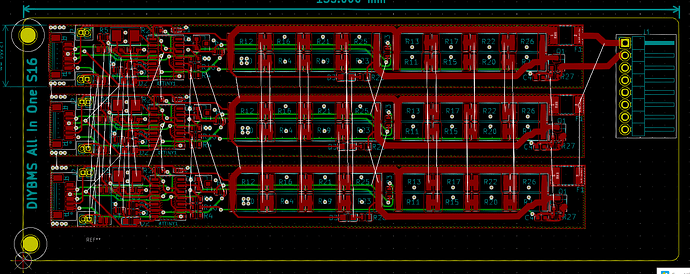
Like this you mean…

I’ve had the same thoughts and design ideas that you mention (this one was started before COVID) however what you don’t see is the feedback I get in regards to why people picked the DIYBMS in the first place.

A lot like the fact that the modules are isolated from each other - this helps avoid wiring issues and the original use case was a ā€œpower wallā€ which could be physically large and having the module next to the cell makes sense.

However I aborted this ā€œall in oneā€ idea - it looked very silly having 16 ATTINY chips on the same board along with 16x programming headers and all the other stuff. I didn’t know what the thermal issues were with 16 cells all dumping heat into a single PCB (and I didn’t want to get into fans etc.)

Ultimately, an all in one board makes sense (which is why Batrium launched one!) but only if you also redesign the entire circuit to remove the duplicate ATTINY (or similar). To remove the multiple controllers then introduces ground isolation issues again (but between the cells this time).

Thermal management is also a big concern with that much power/heat concentrated into a single space.

About 3 or 4 years ago I started looking at the DIY Powerwall scene, harvested a few 18650 cells (couple of hundred) and looked at BMS units. At the time, and still to this day the Batrium system is thought to be one of the best, but it comes at a cost.

Being a ā€œDIYā€ orientated person, I thought I could make something similar - it’s just a resistor and a switch afterwall :slight_smile: although I didn’t and still don’t want to make a Batrium copy.

The project grew from there, the v3 design had issues with communications because it used i2c. Rookie mistake.

V4 has been a great success, a lot of people are using it. In terms of goals:

  1. Originally aimed at power wall - so static location/large sized battery. A lot of people are using these on boats/RVs/Cars now so that also works.

  2. To be safe in so far as you can with a DIY product. This likely limits the voltage to 48V systems.

  3. To gather ideas and feedback from users and collate that into a ā€œsensible systemā€ (but also needs to align to point 2)

  4. Maintain as much backwards compatibility as possible. I don’t want to force users to upgrade if it can be avoided.

2 Likes

Which is why I’m currently in discussion with this forums shop to stock the project and enable an easier route to market with the ordering from China taken out of the process.

@John_Taves, please do not understand me wrong. I am not saying that your ideas about 2 current sensor and more relay are bad/wrong and that your case is too uncommon. If scroll a bit to the top, you will find that I personally asked to add more relays.
My point is - that having too much options will only make more problem:

  1. if you have more boards (different options) then there is potential more places for bugs and more work should be done for testing. Also, more work should be done in case of updates (new features should be implemented for all optional boards) and maintenance would be more difficult.
  2. Having many optional boards would be confusing for end users. I mean when there are too many choices many people are not able to make a final call. There would be endless stream of questions like ā€œWhich board is better?ā€, ā€œWhich board should I use?ā€, ā€œDoes it can this or that?ā€ and so on. The easiest example is the situation with cell monitoring boards: the are only 2 versions at the moment 1 for hand soldering and another for JLCPCB assembly. Check the main forum - people are not able to select from these 2 and repeatedly rise new questions… Imagine they have 10 options…

As for the comparison to the off the shelf products, than it is already a very good competitor with Batrium, which, from my point of view, is best BMS available for sale for lithium batteries. When shunt functionality is added to DIYBMS, I think there would be almost no difference in the functionality between these 2 systems.

So, I would stick to the idea, that there should be 1 version of controller board, that should cover most of the needs of more or less standard application.
As for the second shunt, technically, since BMS is a Battery management system (not PV management system), I would say that it is not necessary. However, since it does not take much effort and costs to implement it, then why not - since many users would probably like this feature.

The only reasonable option with multiple options for controller board I see, is making 2 controller boards: FULL (6-8 relays, 2 or more shunt connections, all interfaces, all I/O-s, display) and BASIC (2 relays, 1 shunt, 2 I/Os, no display). Or something similar.

They are an excellent example of taking a existing design and remodelling it for a different form factor. The code and the circuit are no different to ā€œstandardā€ V4.21 modules.

As you mention, where does this stop 4S 8S 16S - do you have the time to support end users (unpaid don’t forget!) with so many variants of a product, how do you test them so they are ā€œsafeā€ when the code changes. Do you have the space/money to make a lab for every variant?

Its so much easier with a modular system - as there are so many use cases and battery cell types.

Which is why I’m trying to squeeze some i2c ports onto the new controller board I’m looking at so it could be supported as well.

I wonder if some sort of daughter card could be the answer, as you say some people won’t want this, or will need the 48v version. Perhaps a generic i2c header on the controller could be used for multiple purposes?

How do we cross off the issue of 48v being millimetres away from the 3.3v electronics? How do we make it fool proof for the end users not to let out the magic smoke?

1 Like

Jut an idea, maybe stupid. But, if there is a need of an additional current/power measurement (not the main battery shunt, so no SOC and too accurate reading, etc. are required). Maybe it would be an option to use some i2c AI extension + ACS758 current sensors (up to 200A, no voltage restrictions withing our scale, no issues with ā€œmm awayā€). Could be done as a separate board and used for monitoring for multiple chargers/inverters/DC loads.

Which is where I was going with generic RS485/ModBus solution - i2c just isn’t suitable for long cable runs.