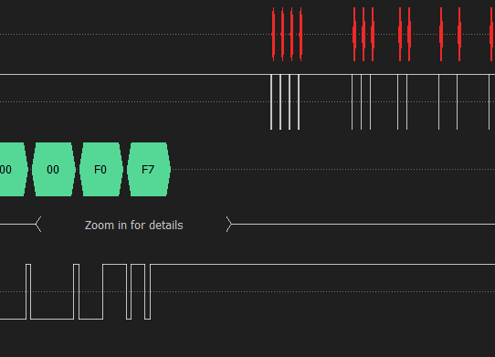
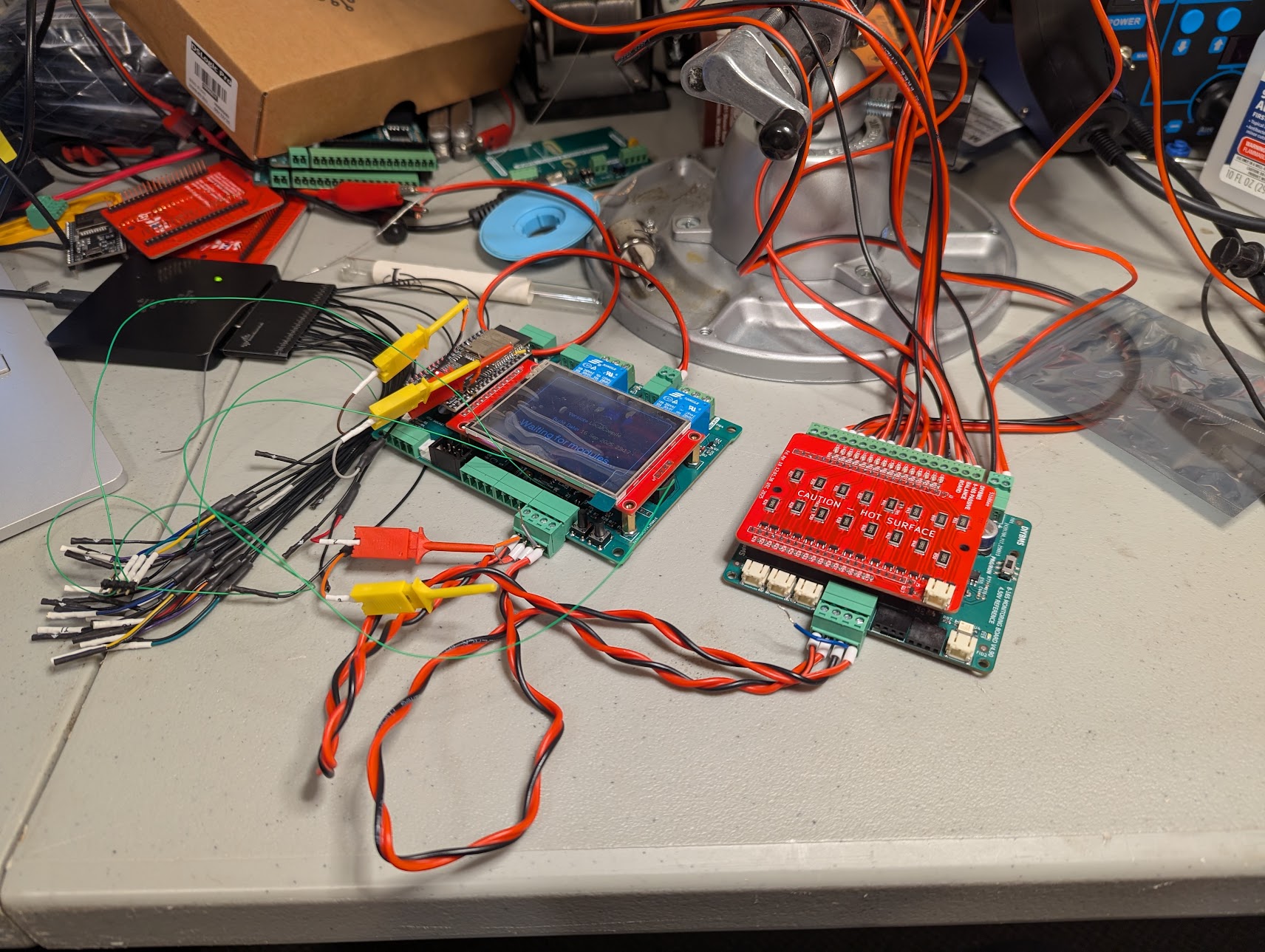
I am currently trying to put together an all in one 16s board and controller for a battery project I have going on. I have the controller and 16s boards built. When I connect the 16s module to the controller the two do not seem to communicate. The controller says waiting for modules. After verifying that the cables were connected correctly I hooked a logic analyzer to the comm cable. I could see both the output to the module and the response back.
After I verified that there is data flowing between the controller and the module I checked the ESP32, pins IO32 (TX) and IO2 (RX). Both pins had data on them. I took a look at the controller code and enabled some printouts, I can see in the serial output of the ESP32 that the module is sending messages and the LED on the module board is blinking in time to those sends. And I know data is flowing back to the controller but I am not seeing any receives in the console log. I am guessing that something is not configured right but am not sure what.
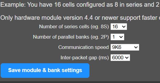
Controller
- FW: main branch commit f909d31 (started using Compiled_Firmware_2025-03-30-15-36)
- PCB: revision a7527b7
Module
- FW: module_fw_V490_AUTOBAUD_VREF4500_genericSTM32F030K6T6
Any help would be appreciated.