Unfortunately, I don’t feel able to start splitting the thread because it doesn’t fall strictly within our code of conduct: “posts shall be edited only when absolutely necessary.”
So your best hope is that all contributors see these last few posts and create a new thread if they feel that is warranted.
You are trying to solve issues with i2c - however i2c isn’t the best solution for this BMS problem, so rather than trying to work around the problem, it would be better to replace i2c with something else - like CAN or RS485 etc.
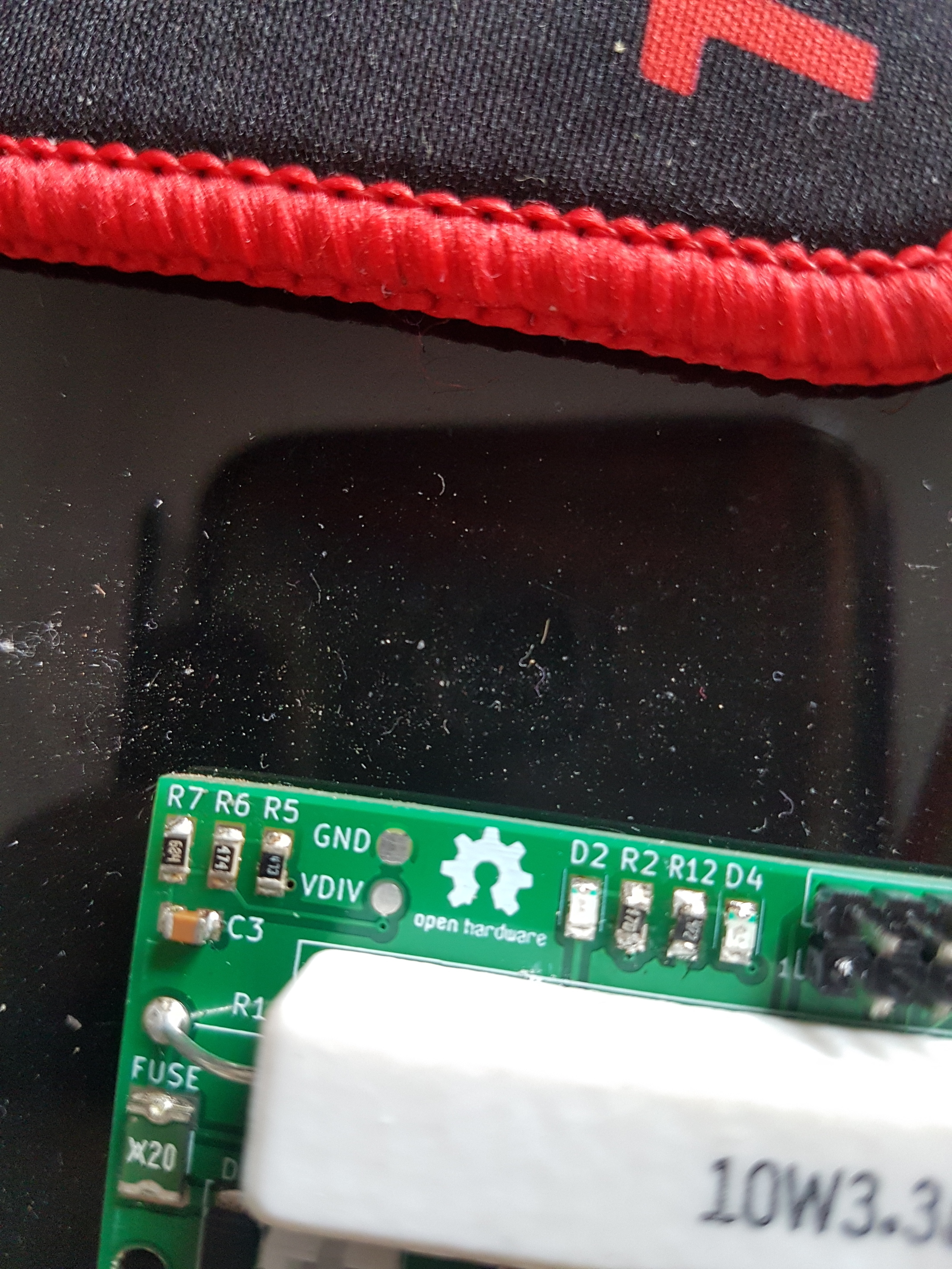
Howdy gents! Before I get too far into the weeds with the LEDs.
Do I have them correct here? The green tinted side facing down are the cathodes.
Blue on the Left and Green on the Right
The green line on your LEDs need to be near the D2 D4 that in the negitive side of the LED as i found out the hard way as my LEDs i got never had any making on them so i replaced all my LEDs with the same style that have a grean mark on the negitive side
Okay thank you! Based on the limited information on the version 3 board it appeared the cathode was facing the discharge resister. Thanks I’ll switch them
If you have a multimeter and put it on continuity the led should light up if black on negitive and red on positive, but looking at the board should be able to see the tracks which would be positive.
D4 should light up and D2 is discharge of cells
Iv changes my colours to D2 red discharge and D4 to green Activity i did have both on blue but i see the colours would have been better choice RGB leds would have been a better choice
For an unprovided module the D4 should little up for a few seconds then go out then using test connection provision all connections if in factory D4 should should stay lite
So far on my side the diyBMS does a good job and has no issues since some weeks now.
As you see there are some guys building this project and for now we don´t have any better so adding PCA9601 is a small task to fix problems. But some of these problems seam to me homemade by wrong installation of I2C or using noisy chinese inverters.
I will try to use PCA9601 to gain some distance up to 3 meters between controller and modules to get it out of the batterie compartment.
As my controller also offers a display, I like to place it visible as one view all OK.
I designed small breakout boards to test it also at module side. Now waiting for JLC
Maybe Version 4.0 comes with CAN ot RS485? yes RS485
Dont you mean RS485 ?
I have TTL to RS485
but looking into using TTL to RS485 to see if i can get my wireless DB6 wifi plug to using ttl to rs485 communication
For all information:
Adam Welch has posted a new video on the net. Where he points out problems of the NTC at the reset port of Attiny85 from temperatures of 5 C or less. - YouTube - diyBMS issue - Voltage Divider Maths - diyBMS issue - Voltage Divider Maths - YouTube
I’ve already updated the schematic diagram to show possible change in resistor values. This is only a problem if you are running the cells outside or in very cold environments.
As mentioned in the video, 18650’s don’t really like cold conditions!
My Powerwall is in front of my house Germany with winter and snow and sometimes cold weather.
Not everyone wants a battery with up to 4200 x 18650 cells in the basement.
**
What resistance values have you now changed my V2 modules still after the status of 09/2018.
ill have to look and see what updates i need to do with my modules
due to one of my modules going into reset all the time now not running at all but waiting for some new componets to come maybe in the new year they be here.


 Germany with winter and snow and sometimes cold weather.