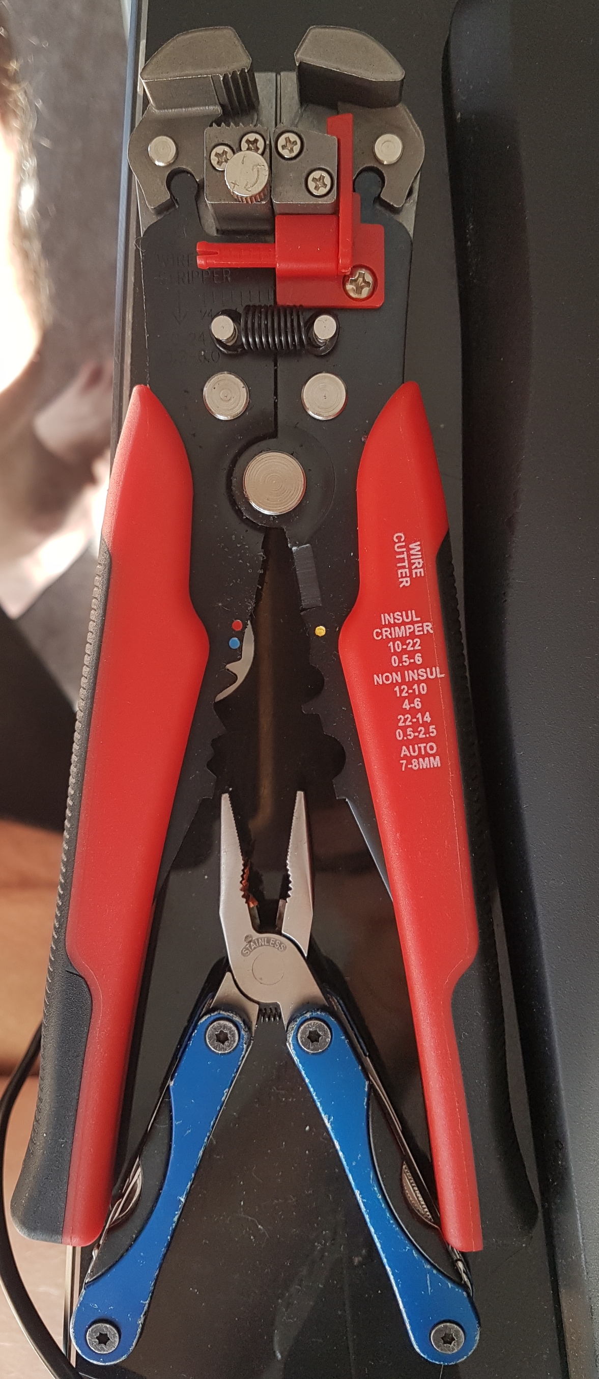
I just used a pear of pliers and a good set of wire strippers
Hi Oliver, I’d also like to use the diyBMS on a boat, your solution looks good! Have you managed to get things running well?
Happy boating!
Tom
1 Like
Update:
It will be more stable with me.
- 14 modules bus 20 cm between all modules + 20 cm ESP + 20 cm additional power supply 3,3v.
- ESP with 5V power supply + 0.5k ohms / 500 ohm resistor
- Additional power supply 3,3v at the end of the module also with + 0,5k Ohm / 500 Ohm resistance
~~ 320 cm bus / 14 modules
and run just under load when loading or unloading just quite stable.
had synonymous tested 2.2k and 1K was best with me 500 ohms will still test 680 ohms when I have time.!
Update: I have made aluminum foil around the data lines for shielding.
**
Question: Does anyone have any idea about programming with Arduino and can help me with the problem with the balance times?
**
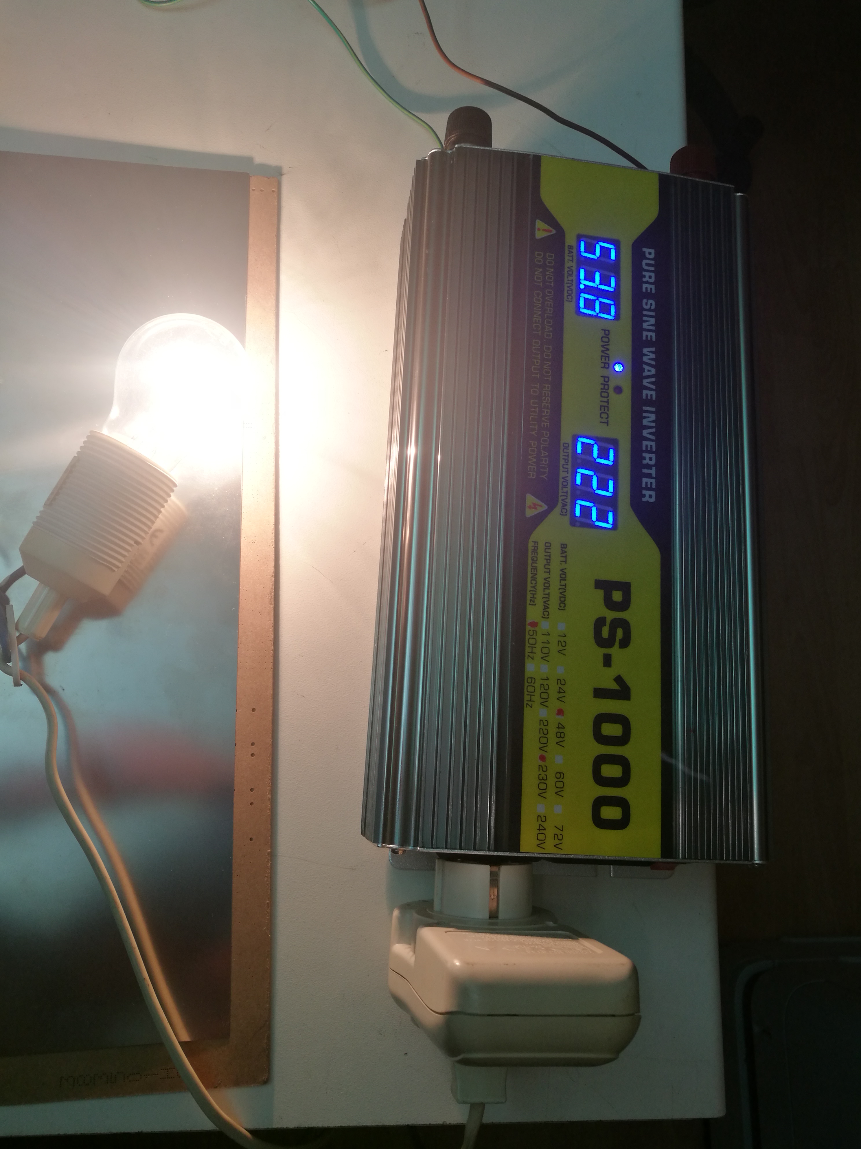
- Load test with 60W *

1 Like
Hi Tommy,
Yes it looks promising at this time, I set a 24V600Ah 6P8S batterie pack up and BMS is working flawless.
as I described above I added lots of funcionality and use an ESP32. I just designed a shiel for it @ JLCPCB to switch away from my development shield.
I realised that one cellpack 6P is always a bit early charged or early low, maybe that has less capacity than the others. I will perform a bottom balancing after using the batterie for a while.
I do not have any issues with I2C, neither when using the inverter or when charging. I use a Victron Multi charger inverter.
I added some more safty checks on values coming from I2C so the software will not let unreasonable values pass.
all the best Oliver
1 Like
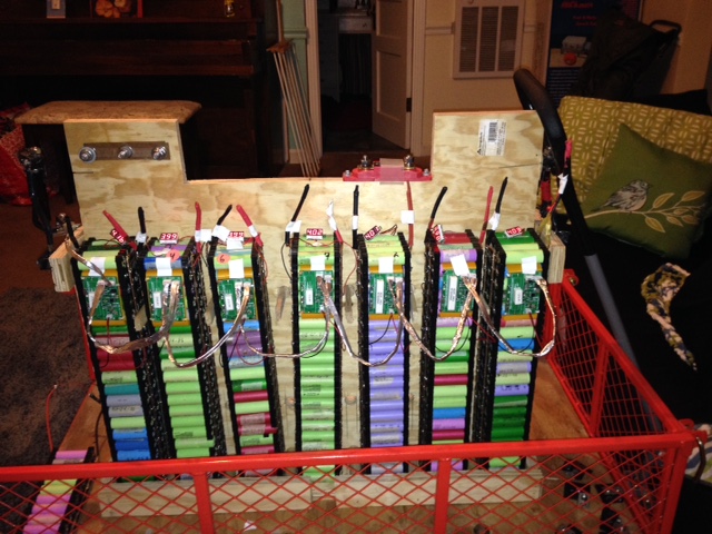
See picture for my status
When I got to the 7th pack, I could not get the wemos to provision. I wrapped all of the 4 pin buses with tin foil. Then the 7th pack provisioned. But the readings are unstable (65V, 4.0V,0.0V).
I am using 1.0KOhm resisitors on the wemos… Any ideas on how to stablize?
Bob
Hi mate the easiest way to provision your BMS is the test controller via serial command it work for me with the new V3 bms thanks to Dirk_Walde game me the info and i tried it worked like a dream.
Thats a very low value to be running on the pull up resistors.
Have you measured the voltage on the module (on the ADUM chip) to see if its still above 3.3v ?
Test with two Power Supply on ESP and on the bus end ![]()
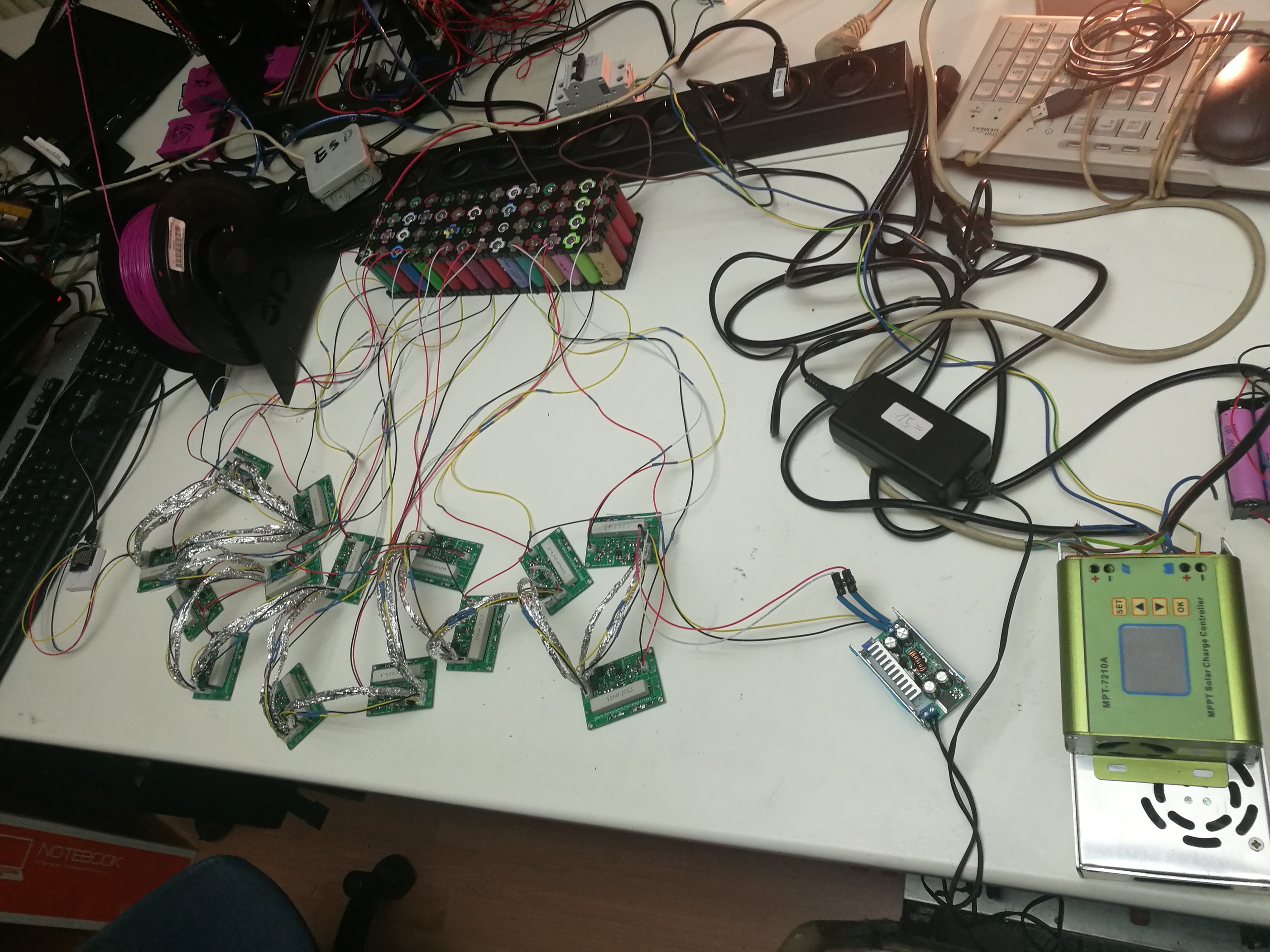
!!! Test with 2,2k / 1k on both ends !!!
!!!
I isolated every single data line.
Not all four lines in the package
!!!
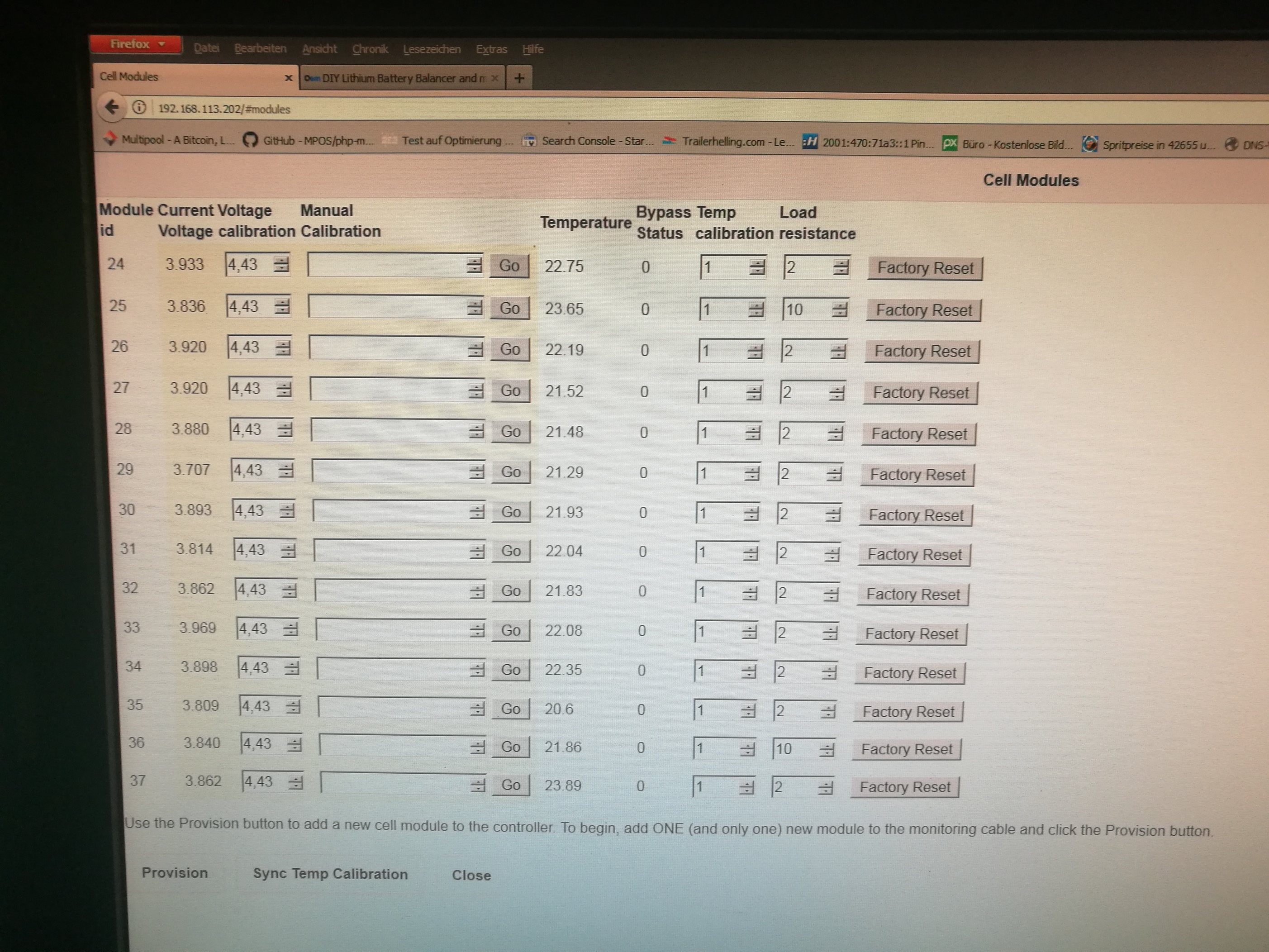
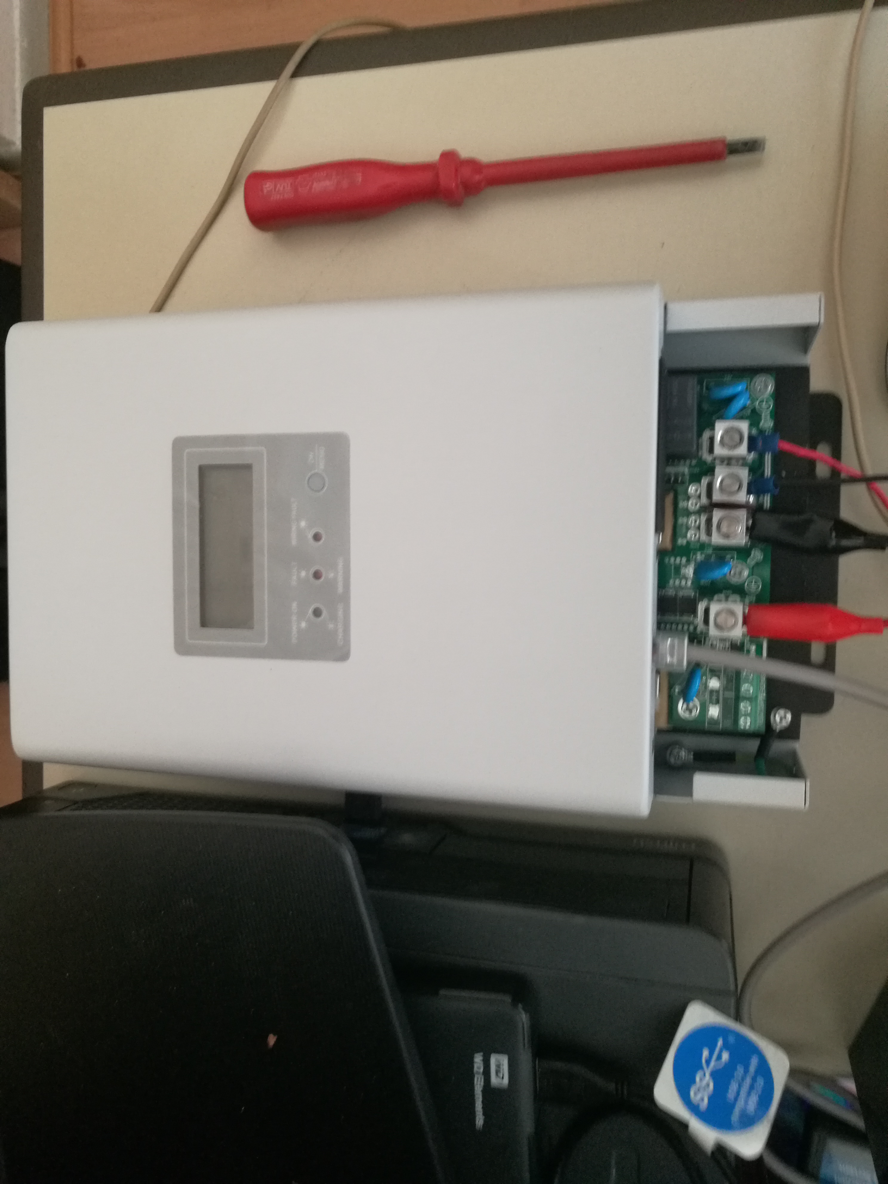
For Test the Moduls
![]()
**
Question: Does anyone have any idea about programming with Arduino and can help me with the problem with the balance times?
**
![]()
Hi dirk
Take a look at Colins coding that may help you GitHub - chickey/diyBMS: Do it yourself battery management system for Lithium ion battery packs/cells
I havent put all 11 modules under full run and charge belance yet as im building the 6p packs for my LIPO Poly packs.
Im running colins coding due to the auto balancing on packs which i like
But i dont have an EPever charge controller has the same charge controller as you do.
Which file exactly.
Just did not find the part for the balance.
or is this in the module itself (Arduino-BMS-Cell-Module.ino)
**
Already have an EMONCMS on a Pi 3 for data acquisition / tacking. Need therefore the extensions for external data acquisition.
**
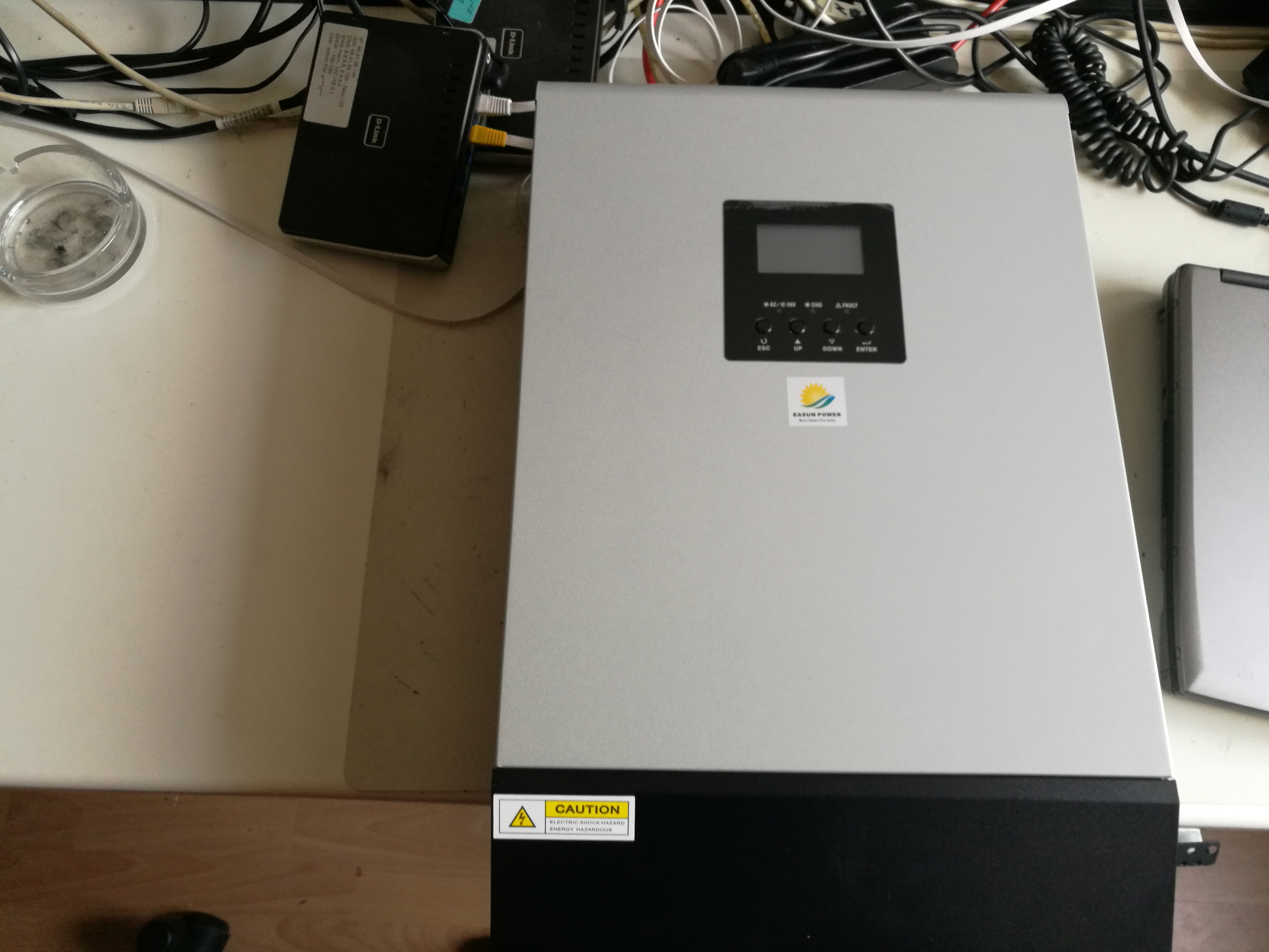
I Have a
EASUN POWER 5000W Solar Inverter 80A MPPT Off Grid Inverter 48V 220V Hybrid Inverter Pure Sine Wave Inverter 60A Battery Charger
and a PCM 60X only Charger
The MPT-7210A is only for testing
You can see My Project at secondlifestorage . com [New German Powerwall - by Walde … at forest]
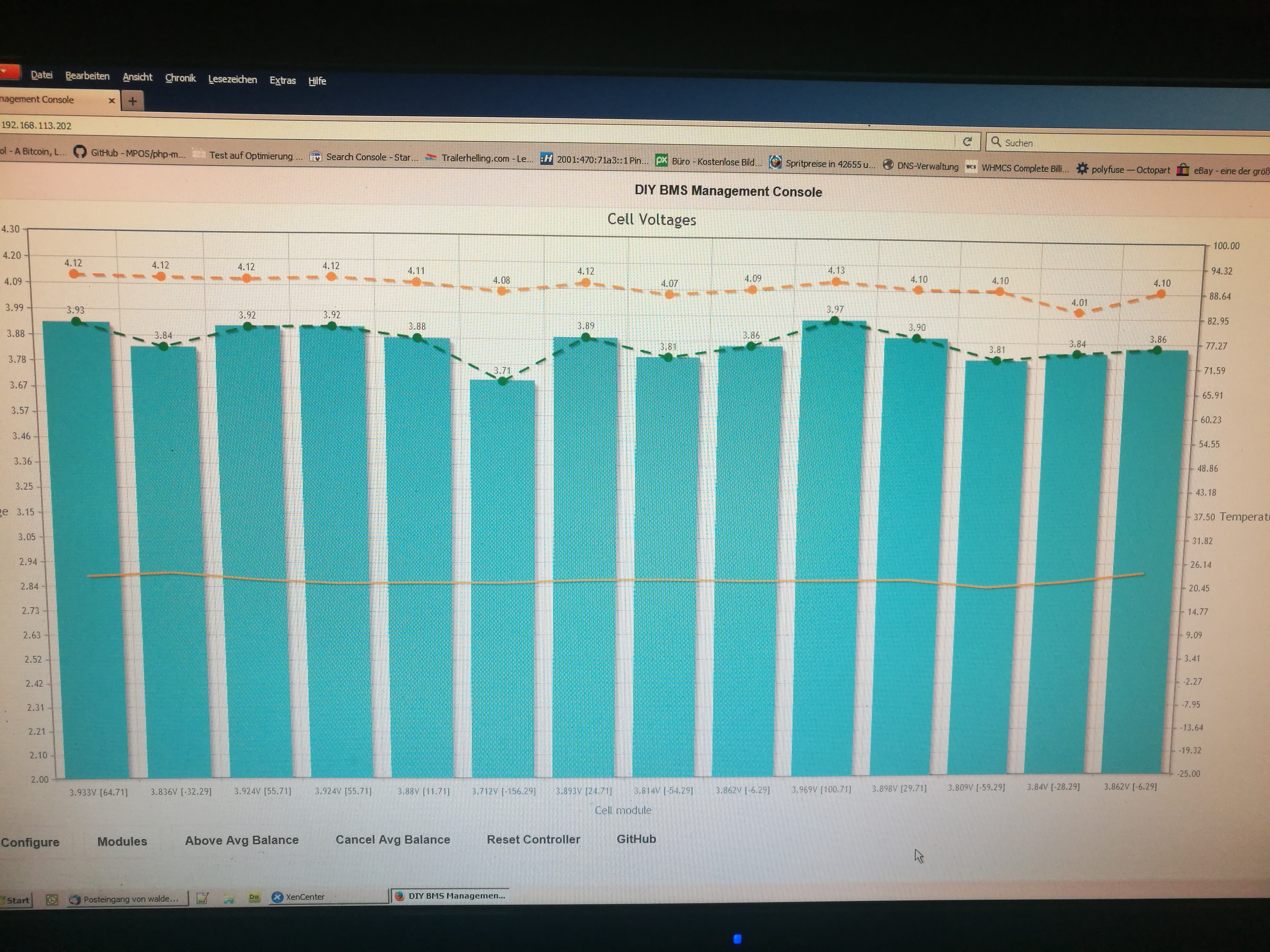
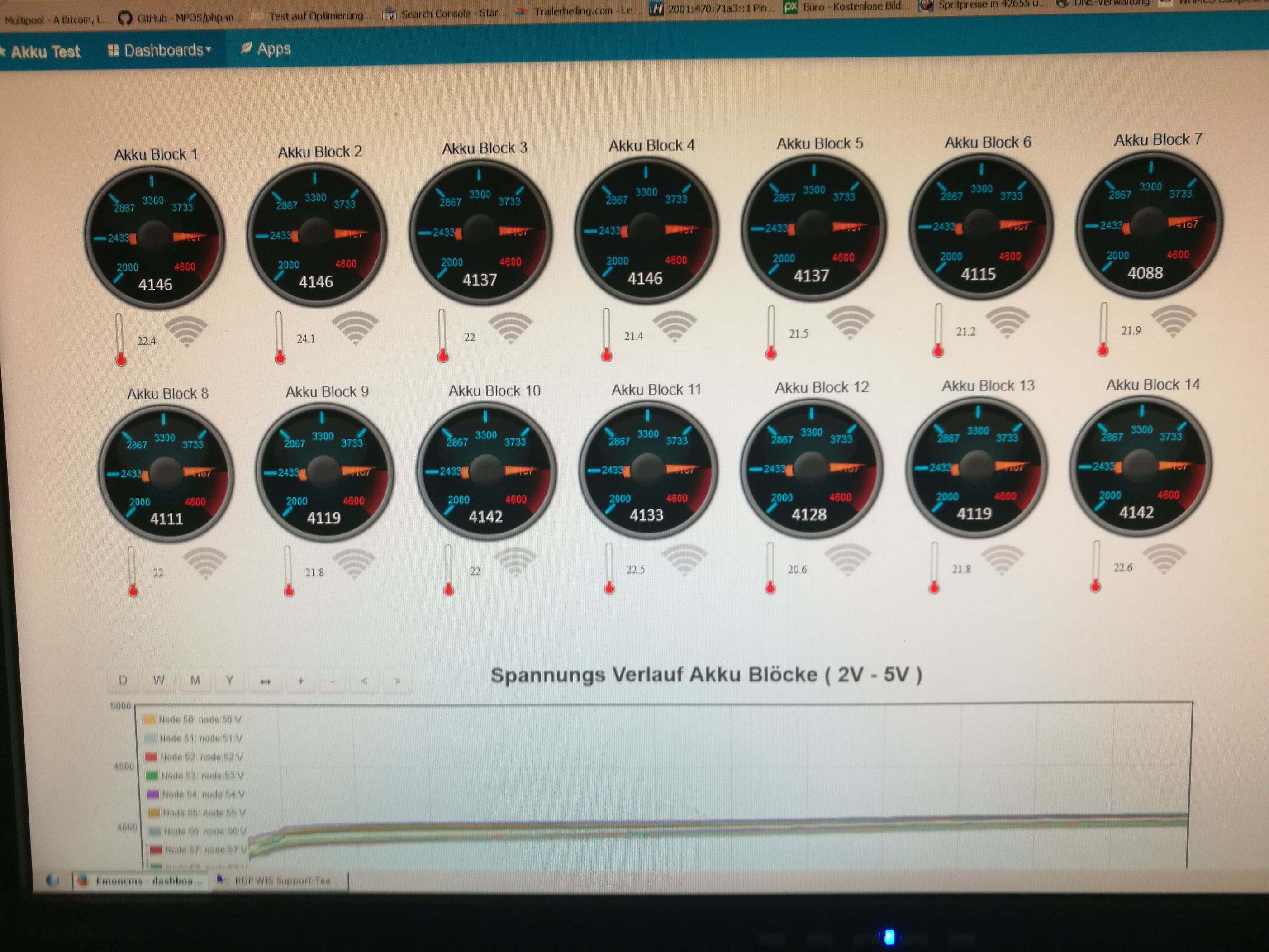
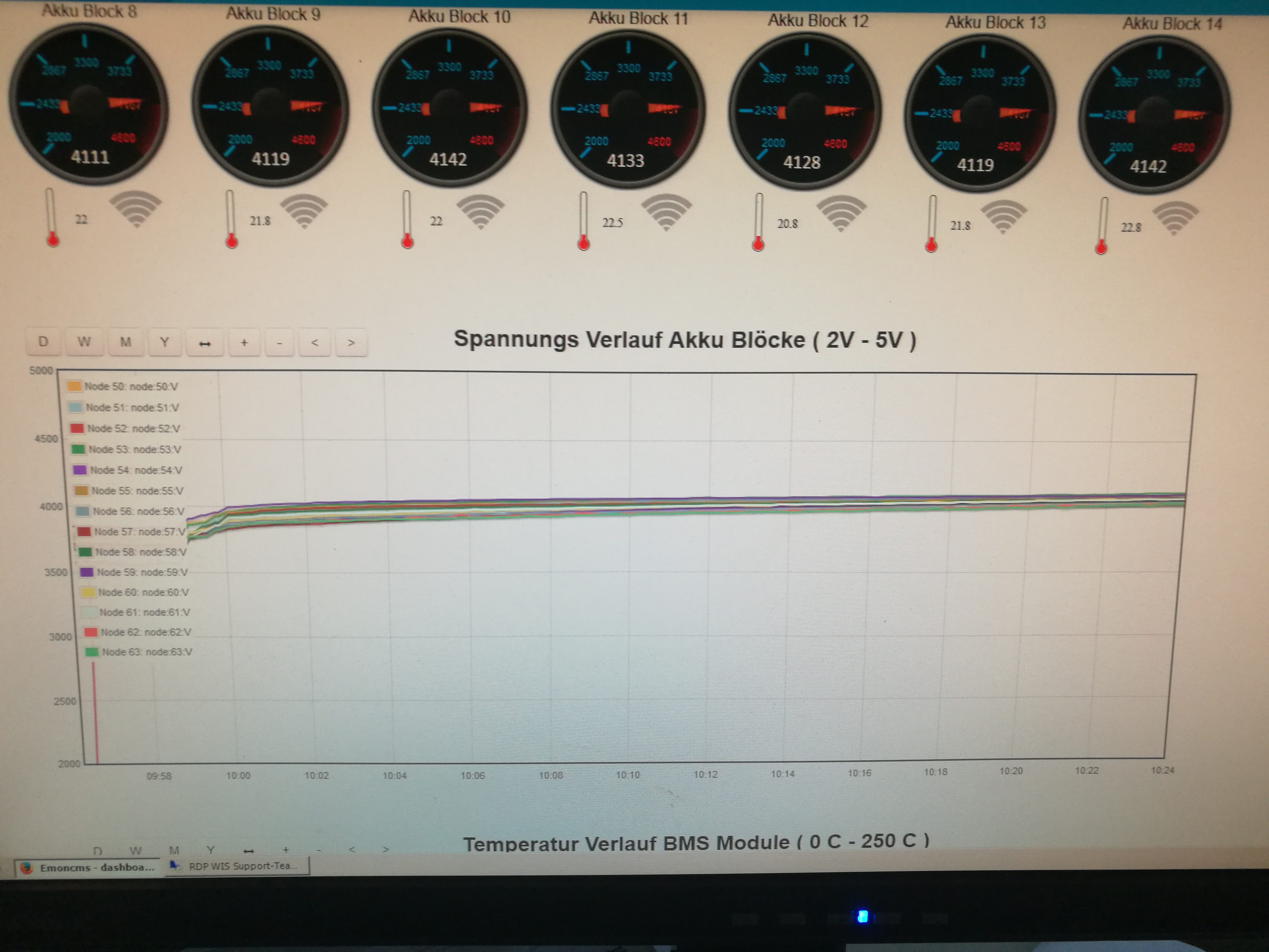
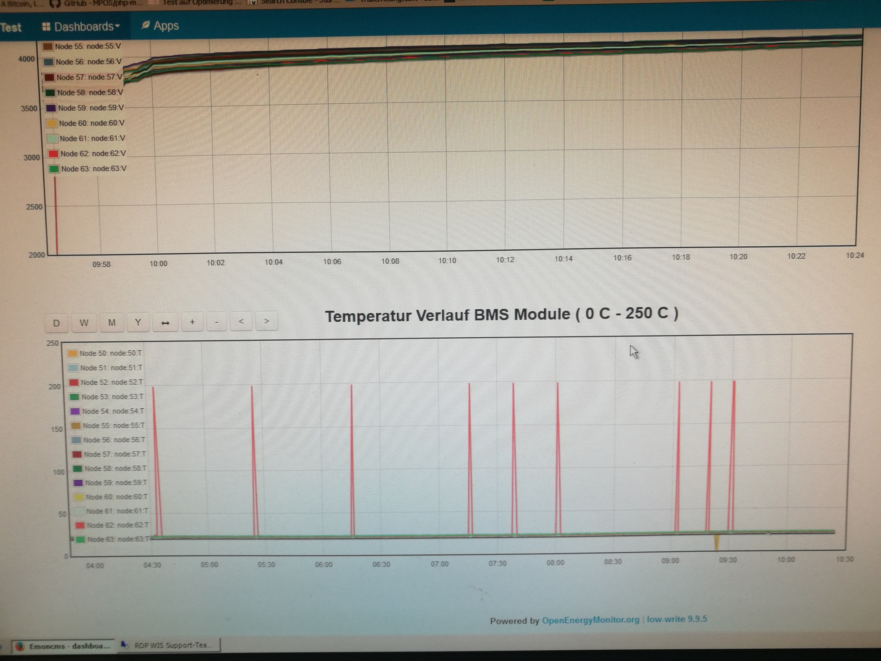
Update: 01.12.2018
EMONCMS on a Pi 3B with DIY BMS on test run
With Temp, Balance Display on WiFI Pic 0/1 Identication = If Wifi On / 1 than Working Balance and Volt Meter
Update: 01.12.2018
Some of my problems are apparently due to EMC Electromagnetic Field.
I have the inverter now times in the next room with 10 meters power line to the battery pack.
And my problems with the I2C are almost gone.
1-2 errors in 2 hours with 60W load.
![]() Recommendation:
Recommendation:
Watch everyone and in case of emergency try to set up the charger and the transformer further away.
1 Like
“Already have an EMONCMS on a Pi 3 for data acquisition / tacking”
Is your Pi3 a model B+ or just a standard Pi 3?
as i have a pi 3 model B+ been looking at emoncms
Colin has written the coding it influxdb part for voltage and auto balancing a to a set value im looking at his coding now.
Most of the scripting is located in SoftAP.cpp but would have to go through and see what you can us and make out of it and where the references are pulled from and directed to so that can be read on screen
Hi dirk
finally got the pi3 B+ to work with emoncms can view device setup now and about to start creating a dashboard
are the widgets apart of the dashboard or they your own images you have uploaded to the dashboard
All parts default by Emon inkl.
image emonSD-30Oct18.zip
Probably worth creating a new thread about emoncms (or search the existing answers) as its a bit off topic for this thread about the BMS!
HELP HELP HELP !!!
Still need help with the Diy BMS for the code in terms of balance!
It will someone know the code better and can help me with the problem.


Hi,
I changed also the balancing routine in the controller, so I am still a bit in the code with my brain.
But my cells are a bit powerfull to be balanced only by the cell modules.
What do you need?
What kind of cells do you plan to use?
As I found out you need to break in the cells with some cycling (as long as they are not compleatly out of line??) after that you may need to bottom balance. I just finshed a bottom balancing project. I use some power resistors controlled by a MOSFET switch and an ACS712 30A current sensor and additional I convert the Voltage with an STM32F103 12 bit ADC and controll also the MOSFET swtich with it.
So tell me where are you now with your progress? how far away from each other are your cell´s? mV??
kind regards Oliver
The solar system is currently not mounted.
But the technology that should run with the DiY BMS
is as follows:
two chargers with total power of 6000W.
Removal 1. Rechargeable batteries S14P100 (1400x18650 cells) = 58v
Expansion 2. 2800x18650
That’s about 90-100A charge current. And then I just need longer balance times than 12 seconds and then 20-30 seconds nothing until the balance turns back on,
I have equipped the DiyBMS systems with R1 (2ohm) = 2A balance discharge yes also the fuse is adapted to 2A.
Only I just can not find the timing settings for the balance in the code.
To set the balance time to 20,30, or 60 seconds.
→ I had already written about the problems in previous news.
**
Your bottom balancing project sounds interesting, I would also be interested in
**
Hi,
I do not remember any timings for balancing, what is done by the cell modules.
The controller calculates the average voltage of the batterie and sends this to the modules. They start to balance the cells that are above this average until its down to average voltage.
thats how I did understand the code.
My cells behave according to this.
I build 24V and 600Ah in 6P8S
My charger is 120A
My inverter is 5000W plus 24 service loads with peak currents of 500A.
even with a 2 Ohms resistor you will not effectivly balance a high capacity batterie if the cells are heavy out of balance. Thats what I experianced the last weeks.
what voltage and how many Ah does your batterie get in the end?
Did you bottom balance your cells with some kind of equipment?
regards Oliver
I have resisted every Diy BMS with 2 ohms at the moment which is after calculation 4,2v / 2 ohm = 2,1A resistance to balances.
The batteries are 1400 cells (18650 4.2V / 2300ma) divided into 14 serial to 100 cells in parallel With a total output of 58.8V max and 202 A which corresponds to 58.8x 202 = 11910 W / 11.91 kwh.
My cell drift is currently not so high but in the summer when loading it could cause a problem and I would like to change that with longer balance times in the code. The loaders are set to 57.4 V max which are 4.1v max per pack.