still have 18 V3.0 boards if any one in australia wants any boards with out having to wait for them to get made and then shipped

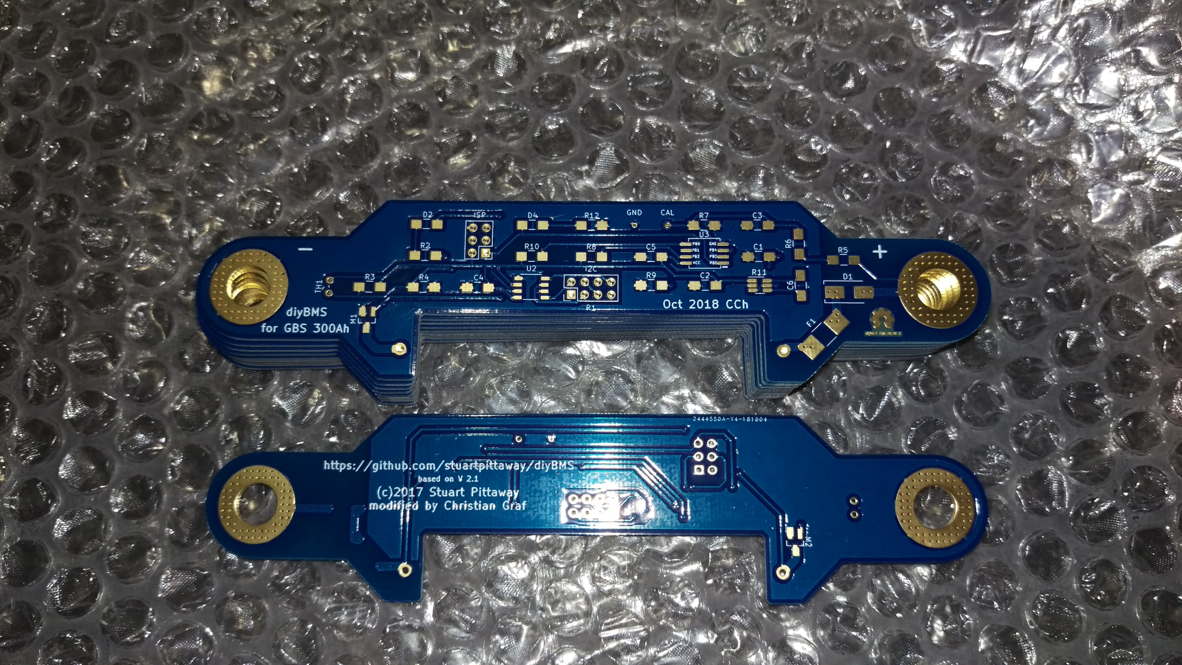

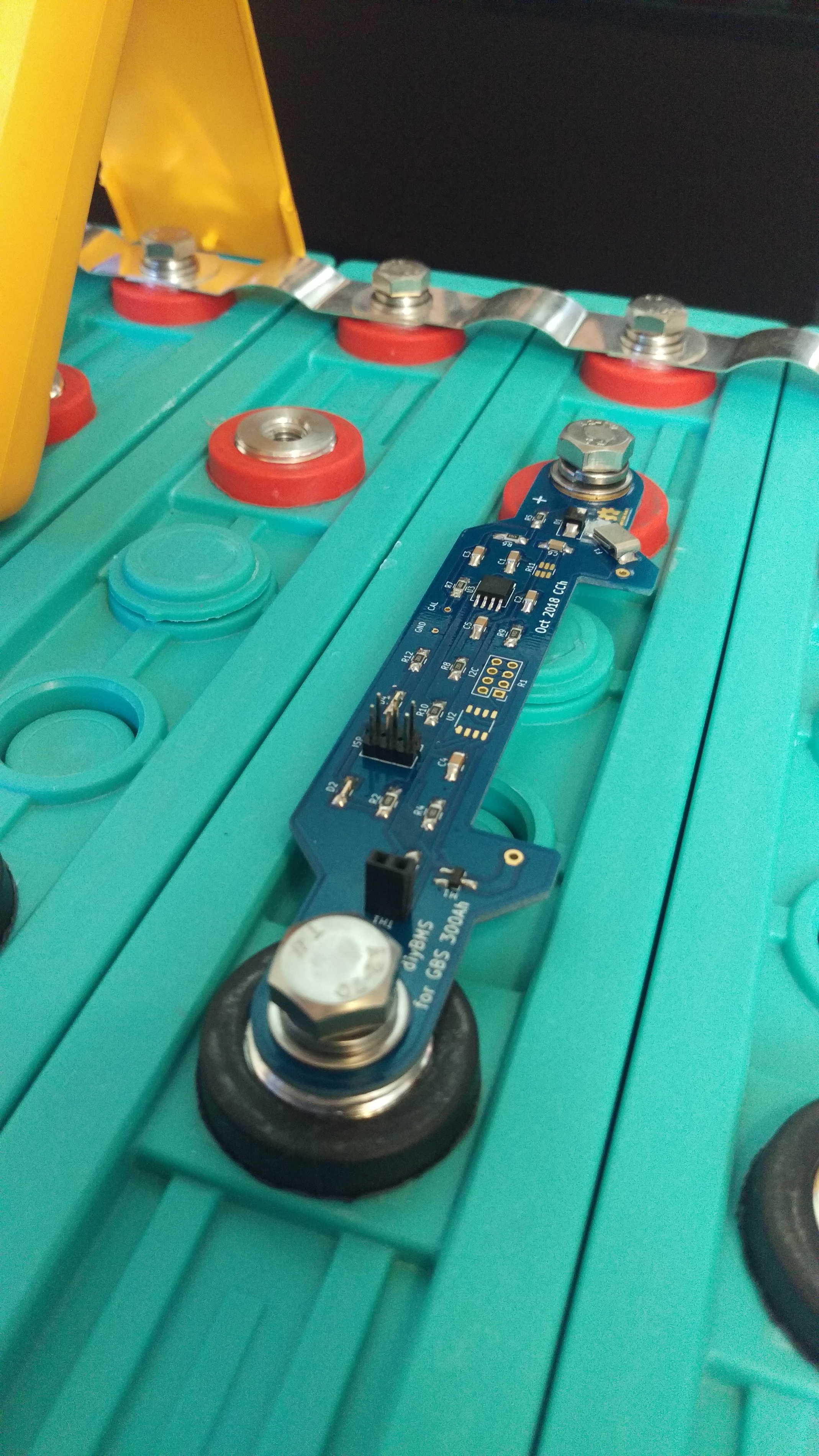
They look awesome!
How much more did you have to pay to get the gold coating

is that usd?
Yes.
If i connect the wemos to the usb while it is connected to the cell module, it says int the serial monitor
Mod: 24 V:65535 VC:nan T:nan TC:nan R:nan
If i understand this correctly, it does see a module with id 24, with a very high voltage and unavailable other settings/measurments.
But in the web console there is no module turning up. If i click on “Provisioning”, the small window pops up and in the serial monitor it says runProvisioning. And thats it, nothing else happens.
What am i doing wrong?
This normally means that the module is returning 0xFF 0xFF bytes instead of the proper reading.
Did you program the ATTINY (including burning the fuse bootloader - 8 Mhz INTERNAL) correctly ?
Hi guys,
I don´t know if I am right here? But it came in my mind to add
an emergency cut_off in case of over or under voltage to the BMS.
I thought of this:
void check_module_quick(struct  cell_module *module) {
  module->voltage = cell_read_voltage(module->address);
  module->temperature = cell_read_board_temp(module->address);

  if (module->voltage >= 0 && module->voltage <= 5000) {

    if ( module->voltage > module->max_voltage || module->valid_values == false) {
      module->max_voltage = module->voltage;
    }
    if ( module->voltage < module->min_voltage || module->valid_values == false) {
      module->min_voltage = module->voltage;
    }

    module->valid_values = true;
  } else {
    module->valid_values = false;
  }

  // place here emergency under~ over~ voltage batterie cut_off routine
  // in case of under or overvoltage a GPIO of ESP8266 will switch
  // to cutoff the load or charger or signal an alarm
  // it would be good to add some kind of
  // hysteresis controll
  if ( module->valid_values = true ) {                    // if module values are valid
      if (  module->voltage > cut_off_overvoltage ) {     // if module voltage is above programmed overvoltage
          GPIO12 = TRUE;                                  // switch GPIO for cut_off switch or alarm
          module->overvoltage_handle = TRUE               // record that overvoltage was hit
      }
      if (  module->overvoltage_handle == TRUE && module->voltage < cut_off_overvoltage )  // if overvoltage was stated and voltage is now lower
      {
          GPIO12 = FALSE;                                   // set GPIO back to low
          module->overvoltage_handle = FALSE;               // reset overvoltage record
      }
      if ( module->voltage < cut_off_undervoltage )  {    // if module voltage is under programmed undervoltage
          GPIO14 = TRUE;                                  // switch GPIO for cut_off switch or alarm
          module->undervoltage_handle = FALSE;            // record that undervoltage was hit
      }
      if (  module->undervoltage_handle == TRUE && module->voltage > cut_off_undervoltage )  // if undervoltage was stated and voltage is now higher
      {
          GPIO14 = FALSE;                                   // set GPIO back to low
          module->undervoltage_handle = FALSE;              // reset undervoltage record
      }
  }
}
Oliver
I did not see that i needed to change the fuses.
This is what avrdude gave back
C:\Windows>.\avrdude -p attiny85 -C avrdude.conf -c avrisp -P COM5 -b 19200 -B2 -e -Uefuse:w:0xff:m -Uhfuse:w:0xdf:m -Ulfuse:w:0xe2:m

avrdude: AVR device initialized and ready to accept instructions

Reading | ################################################## | 100% 0.03s

avrdude: Device signature = 0x1e930b (probably t85)
avrdude: erasing chip
avrdude: reading input file "0xff"
avrdude: writing efuse (1 bytes):

Writing | ################################################## | 100% 0.01s

avrdude: 1 bytes of efuse written
avrdude: verifying efuse memory against 0xff:
avrdude: load data efuse data from input file 0xff:
avrdude: input file 0xff contains 1 bytes
avrdude: reading on-chip efuse data:

Reading | ################################################## | 100% 0.01s

avrdude: verifying ...
avrdude: 1 bytes of efuse verified
avrdude: reading input file "0xdf"
avrdude: writing hfuse (1 bytes):

Writing | ################################################## | 100% 0.01s

avrdude: 1 bytes of hfuse written
avrdude: verifying hfuse memory against 0xdf:
avrdude: load data hfuse data from input file 0xdf:
avrdude: input file 0xdf contains 1 bytes
avrdude: reading on-chip hfuse data:

Reading | ################################################## | 100% 0.01s

avrdude: verifying ...
avrdude: 1 bytes of hfuse verified
avrdude: reading input file "0xe2"
avrdude: writing lfuse (1 bytes):

Writing | ################################################## | 100% 0.01s

avrdude: 1 bytes of lfuse written
avrdude: verifying lfuse memory against 0xe2:
avrdude: load data lfuse data from input file 0xe2:
avrdude: input file 0xe2 contains 1 bytes
avrdude: reading on-chip lfuse data:

Reading | ################################################## | 100% 0.01s

avrdude: verifying ...
avrdude: 1 bytes of lfuse verified

avrdude: safemode: Fuses OK (E:FF, H:DF, L:E2)

avrdude done.  Thank you.
Seems to be ok.
Then i loaded the sketch again.
Now it reads a voltage, but the calibration is not correct, i mean if i put in the measured voltage from the two measuring points into the manual calibration field and click on GO, the voltage that the diyBMS reads gets worse.
If i adjust the calibration factor by hand until the voltage displayed matches the effective voltage, after a few minutes its down to 0.5V, then climbing back up to the effective value.
It does look like the analog input gets clamped to ground from time to time?
Im using a arduino uno as an ISP. Did i change the fuses on the uno?
You can burn the fuses using the Arduino IDE as well - just click the Burn Bootloader option after selecting the correct options in the menus (for chip type, internal clock etc.)
The problem you have seems unusual - if you have a multimeter on the test point does this voltage also drop in sync with the readings from the module ?
I’ve been looking at doing something similar as well - how are you looking to control the external device, you will most likely need some sort of isolation (relay, optoisolator etc.)
Hello Stuart,
- control the loads
Because my expected contious load is about 20 to 30 A with possible peak up to 200A my plan was to use an optocoupler and a heavy load relays (bistable?)
- The charger situation: is a bit more complicated, as I use 4 charging sources
- solar charger
- alternator, with smart regulator
- windgenerator
- 220V Ac charger Victron
the good news is that all devices offer a port to disconnect them.
so in case of emergency charger cut off it only needs and optocoupler and maybe a relay to signal the cut off to these devices. There are no big loads to handle.
I planed that the chargers have to be “smart” charging by itself and in case of any failure the BMS will cut off as last line of defense. In that case I would also add an acoustic ALARM.
At this point it is not clear to me how I will setup all chargers because they don´t talk to each other. So they dont know what the other charger does???
My plan is also to use the temperature sensors to monitor the batteries 24V600Ah 6P8S and add an emergency cut_off by temperature. Maybe it would be also good to cut_off the charger in case of low temperature, because LiFePo does not like to be charged at low temperatures and cells will be damaged?
Did you made any plans to add maybe an OLED display to the ESP?
kind regards Oliver
You may struggle if all those devices are attempting to charge battery cells at the same time.
The solar panels may drive the voltage up on the cells so the alternator/wind disconnect as they think the cells are full etc.
Potentially yes, I’m just deciding if the cell modules need an overhaul in design before too much time is invested in the main controller.
Should we move the design over to industry standards like CAN BUS as the i2C bus isn’t really designed for the purposes we are using it for!
Hi,
Yes its a struggle, but its on most yachts like this. Companys like Victron and Mastervolt (very expensive) try to get more organized charging schemes in their systems but for now I did not see a complete way.
And because this has been this way for many years, I decided to setup my own.
So I need to install a controller that chooses in a smart way the available charging source or combines them. Not all sources are available at the same time and they dont provide full power… preferably the solar and wind should be used first if available. On a sailing yacht the engine starts only some times for manuever or if there is no wind… and the generator is manually switched on if the batteries show they go low…
Oliver
I always made sure the options in the arduino IDE are set up correctly, because im switching between attiny and esp back and forth.
Yes the voltage at the measurment point changes too.
I did also check if i forgot to connect two grouds together or a via got damaged. I also checked the resistor and capacitor values. Its all good.
I try with two boards more, the ADUMs arrived. And since the cells are all at 3.310V i think i can hook the 3.3V of the attiny directly to the cells just for some testing.
What i further noticed is that its not a good idea to connect the thermistor via a pinheader. It may seem to be a good idea, because you can quickly reset the board, but the connection is just not good enough.
Hi,
I think to add an OLED, that shows main values and alarms, to the main controller is not so much work. As long as the hardware/memory resurces are sufficent.
In all it would be great to use CANbus and use standard network RJ45 wires, but then we also may end up upgrading maincontroller to CAN interface…
Are there any issues with the I2C stability?
Oliver
In a electrically noisy environment you may have issues - think so people have used twisted pair cable to help avoid this.