I am still trying to get my mppt charge controller to connect to my pi and then get granfana working
So are you just monitoring the values in the built in web interface? I’d be interested to see if Stuart’s code still gets the eroneous values, i’ll have to switch back and check. I’ve not touched that side so you should get the same issues with his code as well i think. BTW you can do the battery monitoring in grafana independent of the charge controller monitoring.
I’m taking some solace in the fact that your experiencing the same at least.
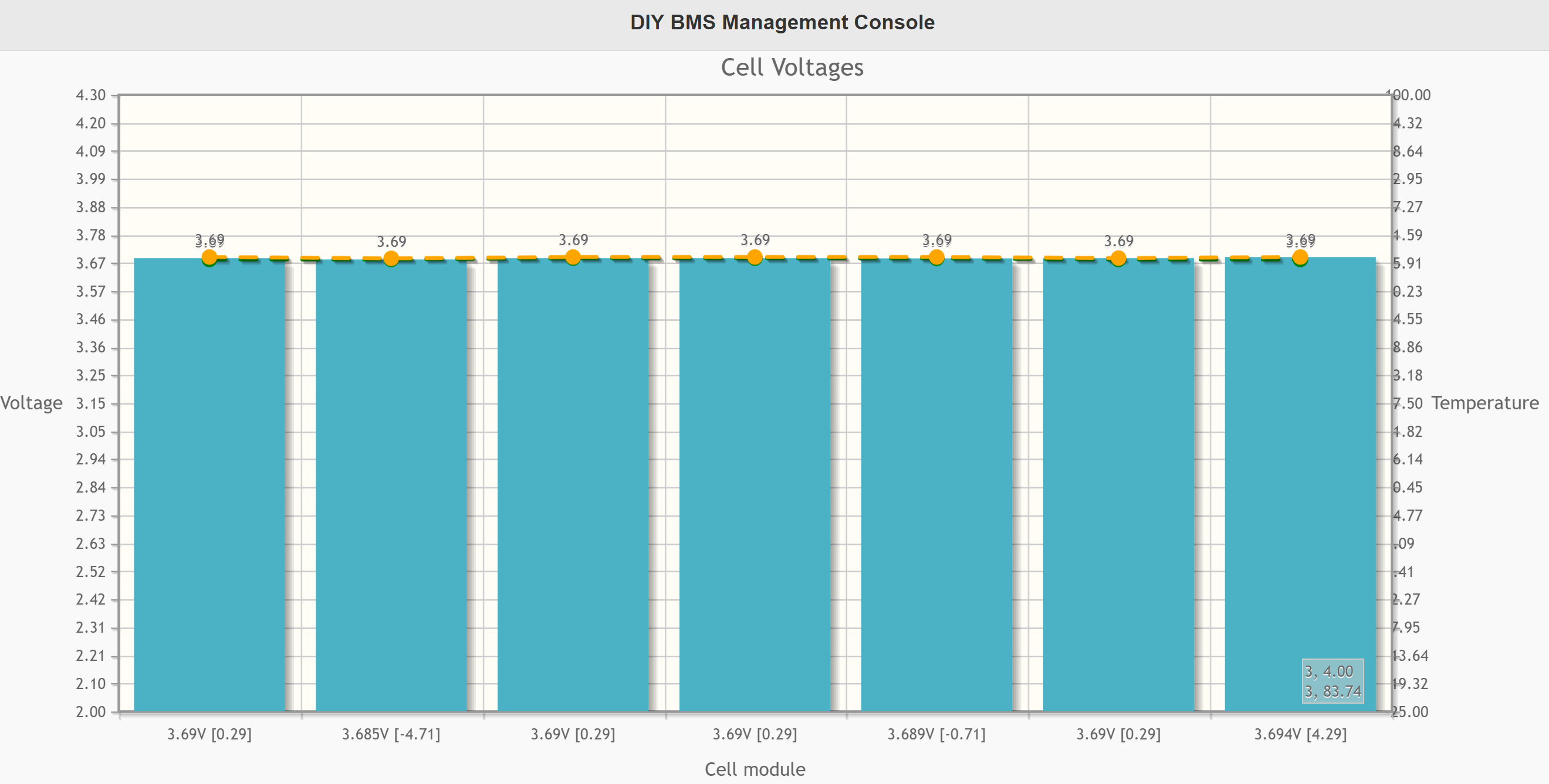
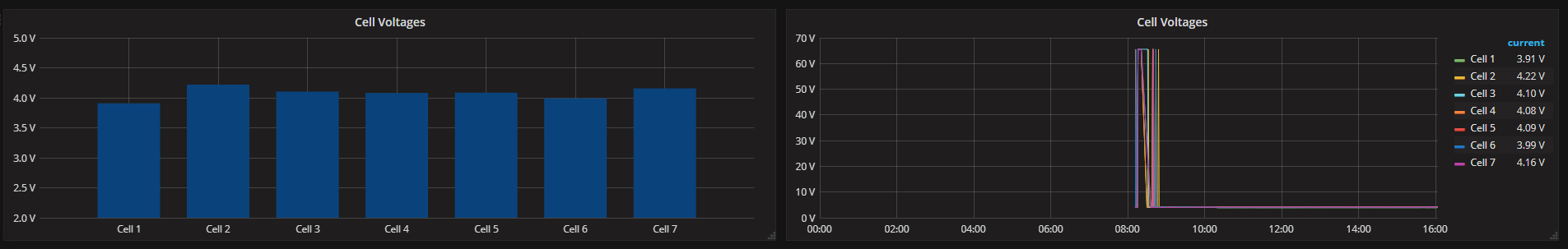
I suspect a 65535 reading is generated when the controller didn’t get a reply from one of the modules, but could also be a software bug
Are you seeing them on your setup also stuart? Just curious if it’s something on my side as i had issues with the pull ups initially and without the setclockstrechlimit change i get no readings at all as the modules can’t be found/communicated with.
Hope you enjoyed Portugal 
I’ve not setup my test rig since I’ve been pack from holiday.
However I didn’t need to change the stretch limit on my setup to make it work!
I2C does have cable length limits which is why CAN BUS protocol are better for this sort of thing, so keep the cables as short as possible.
I guess as your using a nodeMCU and i’m using a wemos D1 and with potentially different cable lengths (32cm here) that must be what is causing the differences. I’ve just modified my code to use a strechlimit of 2000 and it’s working rock solid now with no false values so I’ve hooked it up to my powerwall and getting some nice monitoring
Hey Collin. I am using your variant of the code. I changed the 1500 to 2000 and I’m also not getting the false values. woooooooooooooooooohooooooooooooooooooooooooo. I can finally sleep at night. I am using a nodeMcu with 2 2.2k pullup resistors.
maybe we could use this tutorial to convert the temperature readings into centigrade.
You would need to use the more complex formula
Steinhart–Hart equation
Just a thought - on the ATTINY chips are you both using 8Mhz internal clocks ?
You need to manually program the fuses before you program the chip.
If you are running at 1Mhz it may explain why you need such a slow clockstretch value.
Hi Stuart, that would make perfect sense. I see it’s mentioned at the top of the module code as well, i totally missed it.
I’ve done some code today based on the Steinhart–Hart equation. I’ll pop it on my github a little later when i get a chance to test it properly.
I2C performs well with bigger cables though! Got a 15m setup on 2.5mm2 solid copper wire and it has almost no voltage drop over that 15m!
The issue was down to the fuses not being set correctly on the attiny85’s on the modules. I’ve tested tonight and after setting the fuses correctly I’ve modified the stretch limit back to 1000 and it worked straight away.
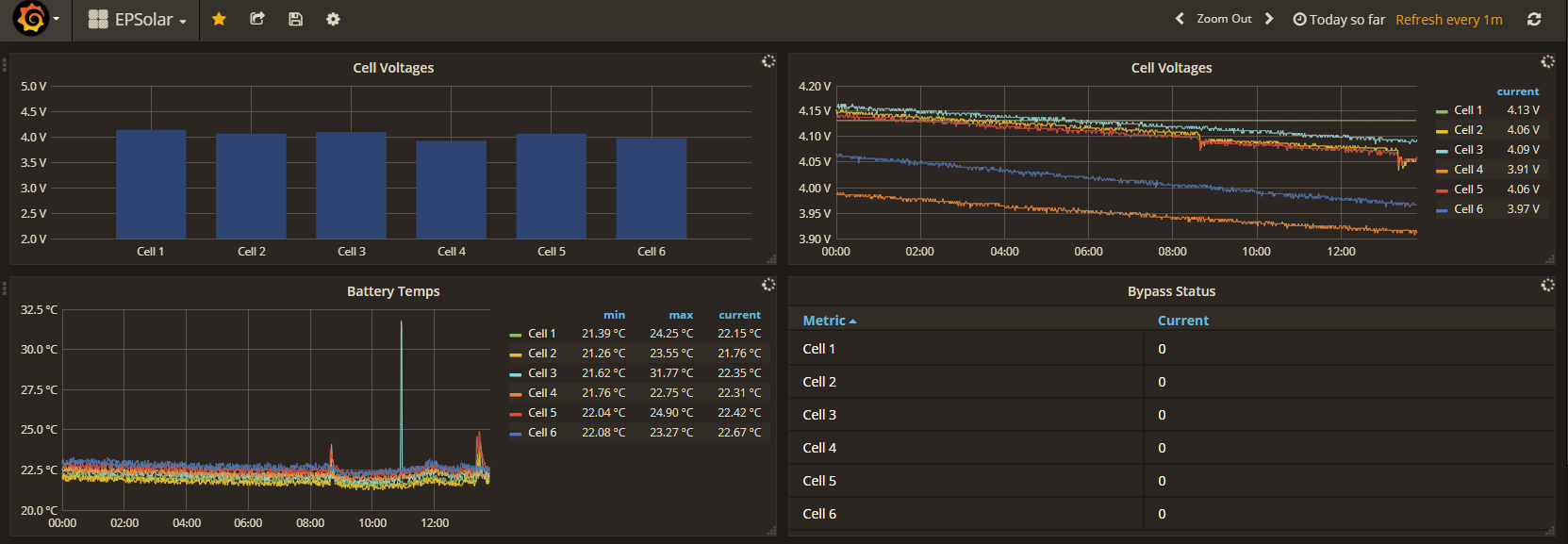
Hi Jman, If your using my fork of the code the readings are in Celsius now. I’ve also modified the grafana upload code so the temps are uploaded to grafana as well as the bypass status as well. Stuart this was the function for the Steinhart-Hart equation. Not as elegant as any of your code but you can get the idea. The values for RT1 and RT2 are from the NTC thermistor datasheet and set for a 10 Thermistor/20k resistor values
float Vin=3.3; // [V]
float Rt=10000; // Resistor t [ohm]
float R0=20000; // value of rct in T0 [ohm]
float T1=273.15; // [K] in datasheet 0º C
float T2=373.15; // [K] in datasheet 100° C
float RT1=35563; // [ohms] resistence in T1
float RT2=549.4; // [ohms] resistence in T2
float beta=0.0; // initial parameters [K]
float Rinf=0.0; // initial parameters [ohm]
float T0=298.15; // use T0 in Kelvin [K]
float Vout=0.0; // Vout in A0
float Rout=0.0; // Rout in A0
float TempK=0.0; // variable output
float TempC=0.0; // variable output
float tempconvert(float rawtemp) {
Vout=Vin*((float)(rawtemp)/1024.0); // calc for ntc
Rout=(RtVout(Vin-Vout));
TempK=(beta/log(Rout/Rinf)); // calc for temperature
TempC=TempK-273.15;
return TempC;
}
Thanks Collin. How did you burn the fuses. Did you use the usbasp?
Yes, stuart has put in the command for doing it with avrdude but i did it through the IDE by selecting the attiny85 as you would prior to uploading, setting the correct speed etc and selecting usbasp as the programmer and then chose burn bootloader. After that i had to re-upload the code, you will need to reprovision the modules as well.