DIY Lithium Battery Balancer and monitoring (BMS)

hi dirk

if you could share a picture of your esp8266 as iv tried using 4.7k on a proto board but dont get any signel to the bms but when i connect my 2.2k proto board everything works but only 9 boards the 10th light is flashing but not provisioning 10cm cables not twisted

I had thought that I would get a grip on it.
Which unfortunately this morning. When turning on the BMS again just garbage on the I2C channel. But I’ll take pictures of the test setup.

Question to all !

I’ve just suspected the code.
How can I change the query intervals of the modules.
Had something of 0.5 seconds read.
How can I change the code so that it is 1 second or 1.5 seconds.

Working System with 10x
Tomorrow I will see if I come to 14x

USB 5V Power PS5V/2A —> ESP8266 with SDA 2,2K SCL 2,2K ----> Moduls 10x <---- 3,3V PS with SDA 2,2K SCL 2,2K

HI Dirk

Great little set up like the idea of the PS 3.3v on the terminating end of your linkage.
No one has mentioned that is needed to run more than 9 modules as i have found myself.
or is the PSU powering your esp8266

I use 2x power. One via USB 5V to the ESP and from the other side of the last module PS 3.3V and on both sides I have 2.2k pullups (4x 2.2k)


!!! NOW: Working System with 12x !!!
but still with problems with the cold start with more than 10 modules


I just need 14 pieces for my S14P100 (18650LI x 1400 pieces) Diy Powerwall System with 58.8V max power 11.91 kWh

This are my cells but will be 74 @ 10000mah each of them 60ah to a bank 12s6p 20amp discharge 5 amp charge

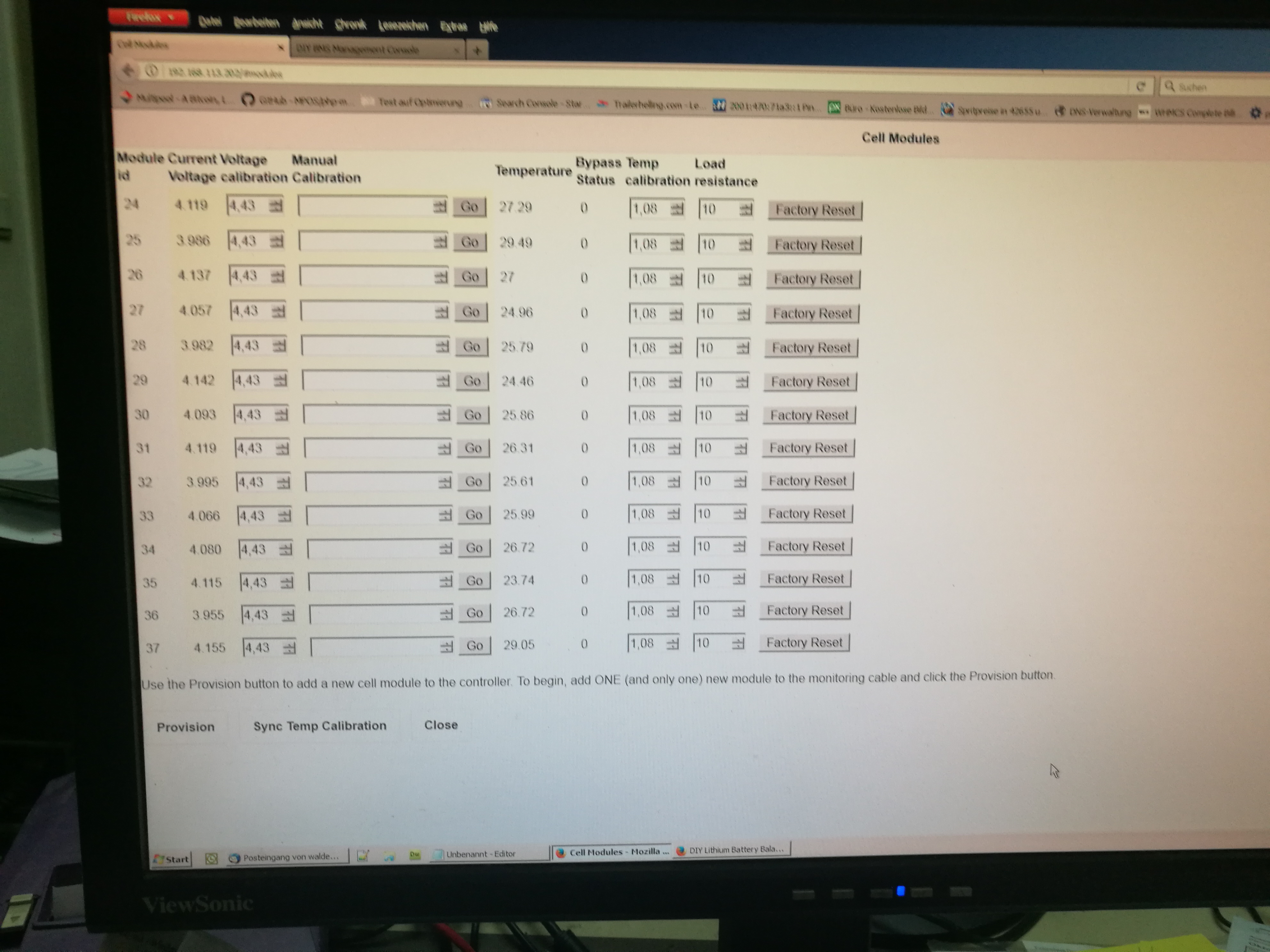
Ok 14 modules are running now.
Unfortunately had 3 defective NTC.
Now let’s see what the next 24 hours bring in the test run.

? A question “aussiegwapo” Brett. ?
Where did you buy your connection cables? Were they already so finished or did you mount the plugs themselves to the cables.

to your problem yet:
I can only recommend you to delete the Attiny again (Arduino example Attiny EEPROM CLEAN) and rebuild with the Board Script. And then via the ESP BMS test software to check if the controller is visible with “X” in the serial console.

And you have me in the normal ESP firmware set a loop for the serial console with output of ID, volts and temperature.

Arduino-ESP8266-BMS-Controller.ino

Line ~~~ 400 +

emoncms.postData(myConfig, cell_array, cell_array_max);
influxdb.postData(myConfig, cell_array, cell_array_max);

  Serial.println(" Aufstellung Module - ID - VOLT - TEMP ");
  for (int a = 0; a < cell_array_max; a++) {
    // ANFANG - AUSGABE CELL VOLT usw module->address
    Serial.println(" Cell ID = " + String(cell_array[a].address));
    Serial.println(" Cell Voltage = " + String(cell_array[a].voltage));
    Serial.println(" Cell Temperatur = " + String(cell_array[a].temperature) + " C "); 
  //  Serial.println(" Max Cell Voltage = " + String(myConfig.max_voltage*1000));
  
    
    // ENDE - AUSGABE CELL VOLT usw
    
    if (cell_array[a].voltage >= myConfig.max_voltage*1000) {
      cell_array[a].balance_target = myConfig.max_voltage*1000; 
       max_enabled = true;
       balance_status = 4;
    } else if (manual_balance!= true) cell_array[a].balance_target = 0;
  }
  if (max_enabled!=true) avg_balance(); 
  max_enabled = false;
   Serial.println(" Aufstellung Module - ENDE ");
  //Update Influxdb/emoncms every 20 seconds
  // ANFANG - AUSGABE Übertragung 
   // next_submit = millis() + 20000;
   next_submit = millis() + 2000;
  // ENDE - AUSGABE Übertragung 
  
}

}
}//end of loop

Update: 18.11.2018

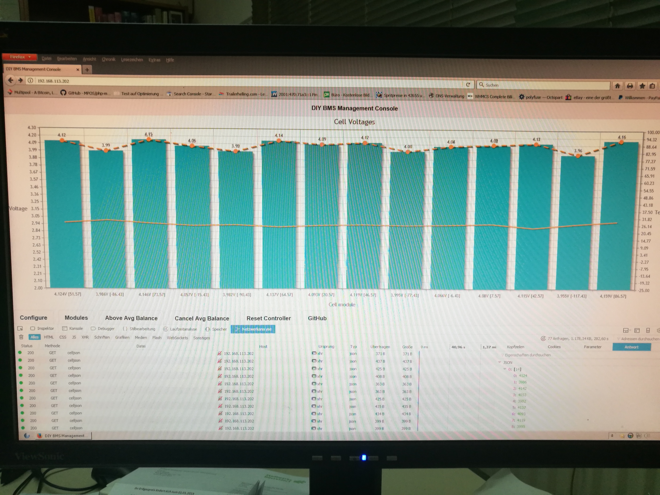
and a little problem with the 24 hour test.
Apparently I still have a problem with 2 boards.
They draw in so much power from the battery that 18650 he has over 2000mah after 12 hours. Empty is at 2v from 4.2v. Since I have to check the REG710NA-3.3 times what’s going on.

Update:
I’ve tested the REG710NA-3.3 and apparently have a short circuit in the output (not soldered clean) or they are defective. I’ll renew the dan tomorrow.

Update: 19.11.2018 for Brett
If we replace the thermister with a resister whats would be the value?
10 k NTC = 10k ohm = ca. +20C

0°C 32,65 kOhm +10°C 19,90 kOhm +20°C 12,49 kOhm +25°C 10,00 kOhm +30°C 8,06 kOhm +40°C 5,32 kOhm

Update 20.11.2018

as expected, there was a short circuit on the pins 3,4,5 at the output of REG710NA-3.3.
Once completely soldered and everything OK as it looks.

Update
now on test run with S14P4 test Pack

1 Like

you had 3 bad thermistors NTC.

I found that one of my i2c chip has a problem

Have 11 modules running

Ill have to get some more compents to build some more boards

Thank you for the tip on using the test controller to provisioning with my modules thats with out having a PS 3.3v on the end of the banks module

I brought my cable from https://www.jaycar.com.au/rainbow-cable-16-core-sold-per-metre/p/WM4516
i made my own cable connectors every connector and power lead is made by hand

Ill have a look in the scripting.

1 Like

Hi everyone, Does anyone have a guide on how to order on allpcb.com, i would love to try the diyBMS v2.1 or 3.0, but i have no idea about all the settings asked :confused: layers , kind, thickness, etc… I think the only option i understand is the quantity XD I know its seems kinda obvious for all of you here, but it isn’t for me at all. Thanks a lot and sorry for popping up with this question

version v3.0 jsbpcb.com

2 Likes

thanks a ton Brett ! really much appreciated indeed!

Can anyone mention dimensions also for the v2.1 ? Thanks a lot
EDIT 2874: well, there must have been an easier way for sure, but i had to install kicad and make manual measurement. 65*45 seems to be the answer :wink:

1 Like

The 45mm is so that the board fits neatly between 18650 once they are mounted in the plastic 4x5 grids

1 Like

Hi Dirk,

I am working to get all ready for you.
I still need to clean up the software a bit and test it before its OK for you.
I use 8 cells 8S and there is a graph that will not support more cells at this time… maybe I can fix it.
You will need the SDcard for my version bcs I store some data on it as I did not store it all in the EEprom at this time. Also there is some CSS and JS on the SDcard bcs I will run the BMS offline at most time and the original concept was for online use only.
The OLED is not important at this time,
I produced a scetch for you, how to wire the SDcard. (only 6 wires)

So where would you like to get the code?

Oliver

1 Like

These can temporarily be replaced with fixed resistors if you need to get the circuit up and running

Why would my i2c be unresponcive.
Is i2c the thurmister.
The attiny85 took programe but the board not coming back after factory reset to get priv order number.
If we replace the thermister with a resister whats would be the value?

The thermistor is connected to the RESET pin on the CPU so if this is faulty, the CPU won’t run.

You could replace it with a 5k or 10k resistor - obviously the temperature readings won’t work, but the circuit should function.

Don’t forget that i2c is NOT designed for long cable runs so make sure you use twisted cable (like ethernet/cat 5) and keep the length as short as possible.

My cables are about 10cm long

Okay, so on each module - check the + and - connections to the ADUM chip (on the i2c side) ensure that the voltage is 3.3V at all the modules. I suspect the resistance of the cable is dropping the voltage below a usable level.

It may also be the increased capacitance on the i2c bus due to the number of devices and total length of wire. What value of pull up resistors are you using?

If you take a module that’s not working and swap it for one that is (you will need to re-provision) does it work as expected? If yes, its probably a cable length/voltage drop issue - if not, its a fault circuit/build.

The cell monitors draw about 10mA when powered from the battery - this is an known and existing problem. Partly due to there being no power control in the ATTINY code and also as the ADUM chip pulls at least 3mA waiting for data to arrive.

Hi stuart

Yes i expected it was a problem with the board as i had 3 that wasnt working at first then used the frying pan on those 3 which got 2 of them working.

i will pull off the main attiny85, ADUM1250ARZ and REG710NA-3.3 from the board as its the only componats that i dont have spares for and rebuild another board with using a frying pan.

I will test the ± on the i2c tomorrow when im how and see what the voltage is on the first module.

ESP8266 mini running 2k2 resisters

tried with 4k7 but no luck

The frying pan method isn’t the answer to everything but can help to avoid solder blobs from hand soldering.

2k2 resistors should be okay, you don’t really want to go any lower.