DIY EVSE build using OpenEVSE Controller flips every 0,5 sec- EV connected, Not connected, EV connected

Hi all. I’ḿ new to the openenergymonitor site :slight_smile:

I procured the OpenEVSE controller and built an EVSE using DIY components, build my EV charger for my BMW i3-2019. All went well, build done, put it in daily use for 2 weeks time, and then it stopped working.

I did “my best” in debuging, read the forum, and ended up whit no 12 volt for the relay to pull the AC relay for starting the charge of the Car.
Glyn was so kind to send me a new module, of the new type (5,5 ?) Thanks :+1:
(old are on the way back)

Module recived and after the rebuild, a wifi update, check of EV state , by resistor and diode. (connect/not connected/ charging) the OpenEVSE controler boot and run whit out any errors.
But connected to the car it “flips”/trickels between EV connected, Not connected, EV connected in loop very 0,5 sec.
The car goes in to connected mode and waiting for charge to start.
but charging never starts.
I procured a new type 2 cable whit socket on, and have replaced it, as the debug test with resistor and diode works.
New cable mounted, but it still “flips/trickels” not connected,Ev connected, not connected… in a constant loop.

Now i need Help, please. what can i check for faults ?

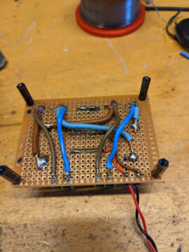
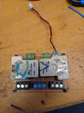
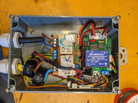
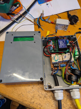
pictures of my OpenEVSE charger:

image

image

image

image

Skjold Petersen

Attached photos to post - Moderator

Welcome to the OEM forum, Skjold.

Will you please post your pictures here. If the place you linked to goes away at some time in the future, your problem and the solution will not be of any help to anyone.

I’m sorry I cannot help you with yor problem, but someone who knows should come along soon.

Thanks.

I’ve just seen the photos of your unit. Before I go any further I just need to point out that you have not purchased on OpenEVSE kit, you purchased an OpenEVSE controller and built an EVSE using DIY components. Please could you edit your post to clarify that you did no use the full OpenEVSE kit.

The relay you have used is not suitable for 32A and stripboard is not designed to carry 32A and the terminal blocks and wire links are too small for 32A. It’s possible to purchase a reconditioned 40A contactor (the same unit we use for official OpenEVSE kits) for £5.50.

Delivering 32A for 10+ hrs is a serious amount of power, careful consideration must be given to the choice of control equipment to avoid overheating and ensure safe operation.

I can’t knowingly help to debug an unsafe setup. Please come back when you have changed the contactor to a CE approved 40A unit.

The t9es1l14-18 relay you are using has an 18V coil, this is probably why it’s not working from a 12V supply and this is probably why the first controller we sent you malfunctioned. The controller has a 12V 200mA rating for the 12V relay output, see datasheet. I would recommend using a contactor with a 240V coil like the one I recommended above.

I would check the earth connection of the controller.

I understand the 32 A concern. In Denmark normal households only have 3 x 16 A phase in to the house.
My DIY setup are only for 1 x 16 A phase. It is meant to run 6-10 A as i plan for a off grid solar setup to deliver charging, but it is not ready for now.

I will procure a different relay and try.

Regarding earth connection. Are the ground on the board link to the earth connection ?
So i can measure earth connection from earth of the 16 A phase to earth to the board, to the car, and to ground on the board ?

Ah ok, fair enough.

The controller is earthed using one of two of the mounting holes, the controller should be connected via this earth connection to your main earth from your incoming cable and the earth from the EV charging cable. All earths should be connected together.

It you’re still having trouble, I would recommend measuring the voltage on the pilot wire, see the explanation of the voltage levels for the different states: Basics of SAE J1772 : Support

It may be a good idea to test using an EV Simulator instead of your car: EV Simulator (KIT) - Shop | OpenEnergyMonitor

Update, I got some time last weekend to investigate more on the problem.
I have grounded the upper and lover mounting holds to the right side (low volt side) direct to the earth on the incoming 230 supply, ground, and the charging cable, ground. (yellow wire)

While waiting for the 40A contactor (relay) and to support the 18 volt relay, I have mounted a “slave” 12 volt relay and a separate 18 volt power supply to “pull” the 18 volt relay, only to test out the DIY setup, as i dont what do damage any components on the controller.

Testing a charge, i still have the same connected, not connected flip stage.
So thinking the only communication the controller and the car do, is the pilot tone and wire in the EV charging cable.

So i tracked down a local brand new Type 2 EV charging cable, cut the remote male end of (the one that normal fit to the the fixed charger plug) and mounted the cable, to rule out if this can be the problem.

Now it works :smiley:
I dont have an oscilloscope only a multi meter.
I have tried to ohm the wire in the defect charge cable, but i can not get it to show high resistance, only 0 ohm.So it seams to work… not. :disappointed:

Another question: You mention that the 40 contractor have a 240 volt coil. can the 12 volt handle a 240 volt coil ? I dont understand that.

The openevse controller has a 240V coil output, see AC RELAY COIL on the main 6-pin connector:

This was SUPER HELPFUL, thank you so much for your follow up post saying how you’d fixed the problem.

I had the same thing happening, the EVSE blinking on and off every second or so like a turn signal indicator (I suspect that behaviour is what caused my PFC-30 charger in my Corbin Sparrow to fail, which blew up the 40 Amp relay in my EVSE.) The behavior was different trying to charge a Chevy Bolt - that seemed like it would start to charge, but the car would then say “Unable to Charge”.

The culprit turned out to be the disconnect button switch in the handle. When the button is released, the microswitch should close, and there should be around 0 Ohms between Common and NC on the switch (there’s a couple of resistors in the handle wiring and in the socket, so the prox pin can determine if the handle’s plugged in or not, and if the button’s pressed or not, by reading one of four different resistances from Prox to Ground.) On my unit, the switch was showing several hundred ohms instead of zero due to contact corrosion - the design of the switch contacts in the handle requires a certain amount of current to flow through it in order to clean the contacts, and the sensing circuit in the car doesn’t send that much current through the contacts, so eventually the switch will get oxide buildup on the contact buttons. This one took about ten years.

As I worked on the switch, the timing of the blinking changed - I think the timing is actually a side-effect caused this way:

Plug in the J1772 and release the button on the handle.

Car looks at the button, sees the circuit voltage at just barely under the cutoff line, and decides the button’s released.

Car engages the charging circuit and pulls in the “I’m Charging, Don’t Move The Car” relay.
That action slightly changes the voltage within the AVC2 device that’s the car’s side of the EVSE control logic - now the voltage on the proximity line is just over the limit, and the AVC2 tells the EVSE board that the handle’s disconnected, and releases the relay.

This action slightly changes the voltage with in the AVC2 device, now the voltage on the proximity line is just under the limit, and the AVC2 tells the EVSE to start charging again, and closes its local relay again.

Repeat until somebody notices and disconnects the handle.

The switch on my Chinese made J1772 cord seems to be a standard KW11-14 mini switch, I’ve got some on order via ebay. Meanwhile I pried this one apart and cleaned up the contacts somewhat - I now get close to 0 Ohms across the switch when the button’s released, which will get me through until the new switches arrive. Works properly on the AVC2 feeding the repaired Manzanita PFC-30, and works properly on the Chevy Bolt.

Hope this helps the next person!

I got into trouble on this point when I built my own unit (actually it is a commercial Chargemaster point that I repurposed using Open ESVE PCBs instead of their’s). Took a while to realise that the mounting hole I picked was not the earthed one. If possible at the next design iteration can both be earthed?