I’m looking for advice at troubleshooting why the total energy usage readings from the emonTx is about 30% lower than what the utility meter is reading.
Background
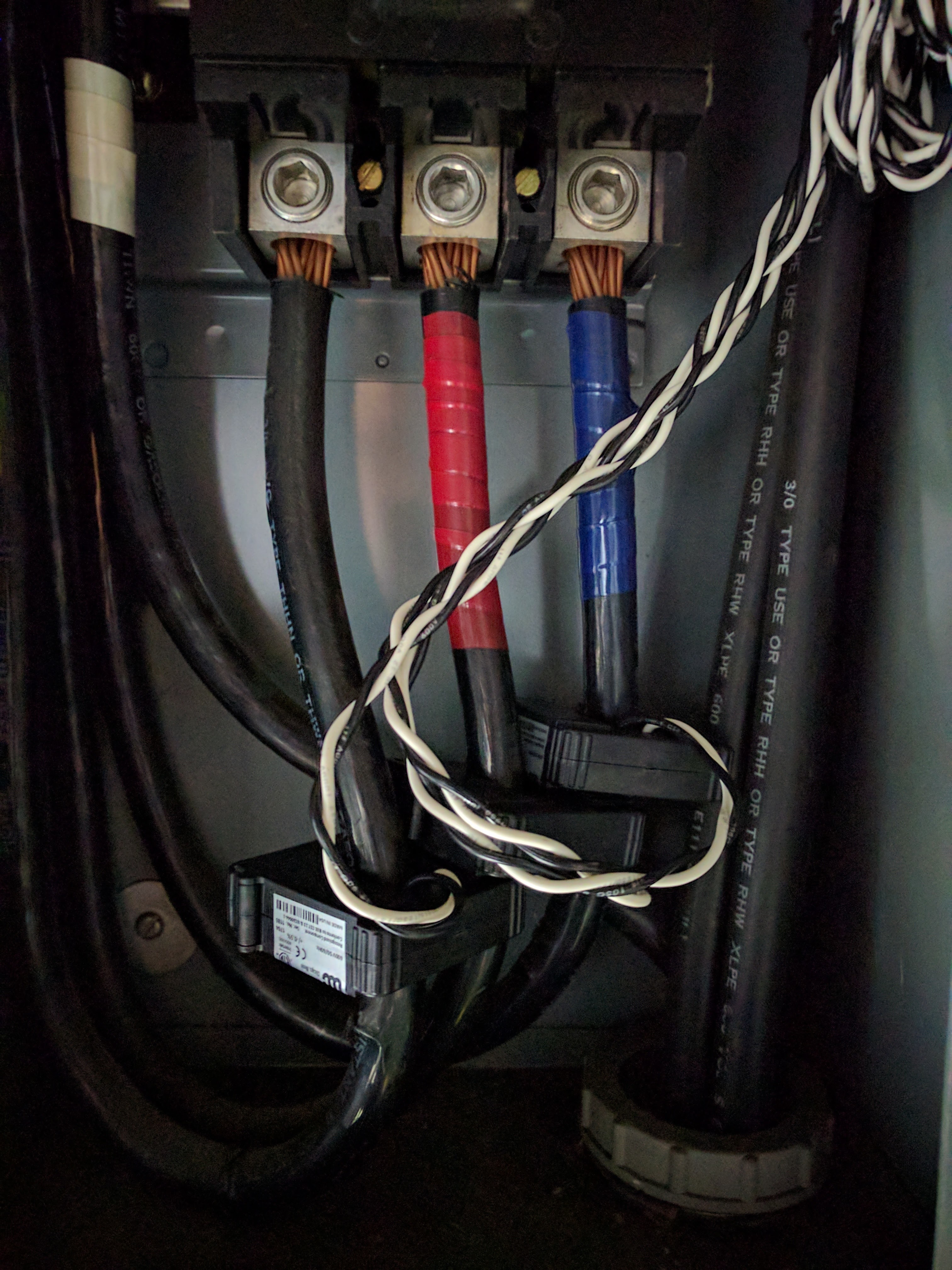
I installed an emonTx v3.4 to measure a 3 phase service 4 Wire (USA 120/208V) coming into the meter. The emonTx runs off the 3-phase sketch. For CT sensors, I’m using Wattcore WC3-200-MA100. I’ve added a picture of the installation of sensors in the panel below and verified that all CTs are reporting positive values. I’ve also tested having all CTs measure the same value off the same electrical main, so I don’t think it’s a CT sensor issue. The emonTx is being powered through the AC-AC adaptor and reads a Vrms around 122V which is accurate.
To do the quality check, I left the emonTx running for 3 days which measured 506kWh of energy usage during that time. I also jotted down energy readings on the utility meter for comparison which measured 756kWh during the same time period. I’d appreciate any advice on troubleshooting this issue. Thanks!
Did you calculate and set the correct calibration constants for your CTs, did you then carry out the calibration instructions in the comments in the sketch file (but following the general procedures & advice in the calibration instructions in Learn) to do the necessary fine adjustments to the calibration?
As well as the current calibration, the timing and phase error corrections will be completely different from the default values on account of both your different CTs and different supply frequency.
Good questions. I did not change any calibration values in the sketch file. I’ve taken a look through the Learn section and the sketch file instructions and want to confirm these calculations. It looks like the default value for amperage calibration is correct.
Amperage Calibration for CT1, CT2, CT3 for the Wattcore 200A / 100mA CT Sensor and the 22ohm burden resistor in the emonTx
Ical = (200A / .100A) / 22ohm = 90.9
As for the timing and phase calibration for a 60Hz system, how do I determine what values to change those to?
From the comment in the sketch file below, I can tell the phase calibration depends on number of CTs connected, but what values do I change ‘PHASE2’, ‘PHASE3’, ‘Phasecal2’, and ‘Phasecal3’ to for a 60Hz system?
// These can be adjusted if the phase correction is not adequate
// Suggested starting values for 3 ct’s [4 ct’s]:
Problem No.1: Although the calibration is correct for your CT, the burden resistor isn’t! You will have a maximum of 100 A (actually slightly more) with the standard burden resistor. But before you change it, you need to consider what the maximum current per phase is likely to be. It may well be that your maximum load will never draw 100 A in any case. If that is so, it’s pointless changing anything.
I don’t live in the 60 Hz world, I don’t have your CTs, so I can’t help you. You will have to do it by trial and error - you will probably need to reduce the values of PHASE2 and PHASE3 (because those in effect are delays, but your mains runs faster than mine, so the delay you require will be less, and Phasecal is a fine interpolation between values of PHASE. I’d set Phasecal to zero, adjust PHASE to get close, then change Phasecal to get the correct power factor of 1.0 on a pure resistive load. If you can’t, go to the next value of PHASE. (Phasecal = 1 is the next value of PHASE.)
As well as sorting out the calibration, you might also want to check if:
the 122V is consistent on all three phases. Ideally you’d measure the voltage of each phase, measuring just one is a short-cut that assumes the phases are all roughly the same voltage. If you get significant variation (as we do in Aus) that would also be a source of error.
dBC, I was thinking the same too, so I went to double check. And the voltages came back within the same ballpark 123V, 124V, 124V for the three lines coming in.
Robert, I don’t expect current exceeding 100A on any of the phases on maximum load, which means I can keep the same 22ohm burden resistor and 90.9 amperage calibration.
As for the for the phase calibration, is there a way to calibrate without a pure resistive load? In this case, certain inductive loads need to stay on (i.e. refrigerator)
No - unless you know the combined power factor, which is extremely unlikely.
But what is the problem with switching refrigerators etc off for the few minutes it will take to calibrate the phase/timing? You should get all 3 phases done in 10 - 15 mins maximum. The 3 sets of settings are not interdependent, so you can change a value in each of the 3 phases, load the sketch, check the resulting value of power factor (say 30 s for it to stabilise), repeat until you get close enough. (Write the numbers down as you go, else it’s easy to get lost.)
@dBC
I’d love Megni to be able to offer a proper 3-phase unit, but the suggestion has thus far fallen on deaf ears. Robin has done a 3-phase diverter that does it correctly, but he’s wrapped up in red tape with it at present.
In the meantime, 3 emonTx’s or the approximation sketch is the best that we can do with what the shop sells.
Just reading through this thread as the whole three phase thing just seems to keep coming up. I’ve got to say that I don’t believe minor voltage variation or phase differences would amount to a 30% inaccuracy. It was right to check the CT calibration numbers, but since they seem to jibe with the theoretical math, I’d suggest you probably want to look elsewhere for the error.
On of the first things I would do is put a clamp on ammeter on the legs and compare the amperage with what is implied by the instantaneous power readings (watts/volts) to see if you are anywhere in the ballpark. 30% is pretty much out in left field.
Have you done the maths? The timing error is hardly minor. That alone, even assuming the same phase errors in the transformers as the ‘shop supplied’ ones, gives rise to an error of nearly 14% overall on a balanced, purely resistive load. But if the third phase happens to be fully loaded and the other two not loaded at all, then the error is 33.1%.
It is most important that @nelson carries out the correct calibration procedure to get the best accuracy.
Here is what I had to say about three phase in another post the same day.
I have to confess that I haven’t looked at the algorithms that are being used to estimate power in a three phase system using only one of the legs for a voltage and phase reference. I defer to you, as the in-house power engineer. If you say there is a potential for 30% error in your gear if the CT phase shift is off, then I believe you.
My limited experience is with my IotaWatt monitor which will match a three phase meter within a couple of % with nothing more than the interactive voltage calibration procedure.
I’ll stay tuned to this thread to see how you resolve this fellows problem with calibration and hope to be better informed by it in the future.
I’m pleased to see that you have made that provision, because it immediately removes many of the limitations of using a single voltage, which are clearly spelled out in the sketch.
I’ve been ruminating about this since posting earlier and I have some thoughts that I would be interested in your opinion. I have an idea based on some asumptions that I would like to validate:
The three legs in a particular installation will be, within some fairly low tolerance, 120degrees apart. They are intimately linked by virtue of being produced by the same spinning generators. (maybe the future, with DC transmission and inverters will change that)
This is not much unlike the “split-phase” in the 120/240 power system here in the USA. The main difference is the two legs are 180 apart and the math works on the alternate phase by either reversing the CT or reversing the sign of the result.
Even though in the US split-phase system voltage is assumed to be equal in both legs by virtue of the center-tapped transformer, the reality is that the resistance of the neutral leg causes variations of as much as several% on a continuous basis. Yet we ignore that and still get pretty decent results, especially when total power is well balanced.
Using those assumptions, I can theoretically measure any of the three phase legs by specifying a phase lead on the VT of either 120 or 240 - the correction is easily determined by looking at the phase difference between the (sinusoidal) voltage and current sense signals and separating the gross (120/240deg) from the fine (VT vs CT phase lead) and adjusting appropriately for the indicated gross + the calibrated VT vs CT.
This exercise has given me food for thought in that I have been oversampling to do phase correction, when it would be just as accurate to “wrap” back to the single cycle sample using a modulo function. (should work with high sample sample rates representing less than one degree of the cycle).
I’m going to revisit this in code and maybe set up another 3-phase test site to experiment.
As explained in the 3-phase article, 120° will only be true for a balanced system. Once the system becomes unbalanced, the angles are no longer exactly 120°
No, we’ve had a d.c. link with France for over 50 years.
3. In the 3-phase case, the transformer impedances could be expected to play a larger part in supply regulation. In the U.S. final distribution transformer, the same winding and the same limb of the transformer supplies both legs, so only the winding and cable impedances affect regulation, whereas for a 3-phase transformer, the windings are inevitably on different limbs and the flux density can well be different too. In both the split-phase and three-phase cases, a balanced load means no neutral current.
You can only do that if you know the power factor of the load. In general, you don’t know that. When we say in the calibration instructions “use a resistive load”, we are defining what the power factor and the phase difference between current and voltage will be (unity and zero respectively), so that the apparent phase difference can be measured and compensated for.
You have a slight advantage in the US as the tolerance on frequency is tighter. For us, it is 50 Hz ±1%, and of course a frequency change reflects into the delay for the timing of the voltage reference for the 2nd & 3rd phases.
By far the ‘best’ way is to treat each phase independently as a single-phase supply. If you have a 4-wire supply, you have 3 phases of course, 3 currents, voltages and powers, and all have a meaning. If it is 3-wire, then you treat one phase as a neutral and measure the other two, still treating them as single independent phases. Then, although the individual values of current (2) and voltage (2) have a meaning, the two power values on their own are meaningless, only their sum has a meaning. You can measure and know the third voltage and third current, but you don’t use those in power calculation.
I think there you’re describing exactly what the emonTx 3-phase sketch does. If (as I think) you’re storing a complete cycle and not doing the maths in real time, then you already have everything you need. It might be tricky if you’re double-buffering though, because you need a circular buffer.
I looked at the eMon sketch and I can see that it would have problems that are really caused by the granularity that is the result of the low sample rate. It’s pretty hard to apply a phase adjustment when one sample represents 15°. But I get the idea.
I made some minor changes to IotaWatt to allow larger phase correction than had been the case with the simple correction for the net shift between VT and CT. Now when I add 120° or 240° to the net VT-CT correction, and apply that with a purely resistive load, I get a power factor of .50 - which is what I would expect as that’s the cosine of 120 and 240. Also, if I add 180 to a circuit, the power stays the same but the sign is inverted, which is again what I would expect with the cosine of 180 being -1.
So if I examine the apparent power factor with no gross phase correction, and find it to be -0.5, then I could recalculate using the same vectors but adding that 120° shift and come out with pretty much what would result from a 3-phase system where all of the legs are equal voltage and exactly 120° phase sequenced.
So that brings me back to the original question of what is a realistic estimate of the voltage and phase differences in a typical unbalanced system that someone might use one of these devices on? Voltage variations of 1-2% will result in power errors of 1-2%. phase errors are more tricky, but when I vary the simulated error by 1-2 degrees, I get 3-5% error. I suspect that would be quite a bit less when the power factor of each leg is relatively high, say .8 or better.
In any event, I’m going to set this up on a real world 3-phase building and see what happens.