Do you find that your 1deg setback actually saves on running cost, compared to maintaining a single fixed IAT?
It only saves money because I have a cheap rate tariff between 23:30-05:30. So I can let the house cool down slightly from 19:00 and then refill the walls with heat at 04:00. (The saving is of the order of 40p per day; on Intelligent Octopus)
If I didn’t have the cheap rate tariff the benefit of ‘set back’ would be negligible.
Hi Andre,
Regarding your response quoted above, I initially thought I understood this, now not so sure ;o)
Shouldn’t the cycling only become a factor when the house has reached desired temperature whilst in expanded mode?
I thought that the flow temp is dictated just by the outside temp and heat curve, so will remain constant up until the house reaches the temp desired?
Ours seems to be cycling when your desired room temp is still 1 degree away (I have no 3rd party monitoring tools, just from looking at the controller every 30mins or so to get the stats you asked for.)
You’ve got quite a low dT (difference between flow and return temperature) - less than 2K. So the 0.4 K underestimation of the flow temperature leads to an underestimated heat energy and thus COP of more than 20%.
No worries, all this gets quite confusing. I am not aure what exactly the expanded mode does, I’m using the pure weather compensation myself.
Your understanding of the weather compensation is correct. The key to understanding the cycling is that the system aims to keep the flow temperature constant but fails to do so because it can only deliver more power than required.
Let’s look at a hypothetical example. Say the target flow temperature is 30°C and it’s 10°C outside. At this outdoor temperature, your hypothetical house requires a heating power of 1kW to stay at your desired temperature, let’s say 20°C. The hypothetical radiators in your hypothetical house are dimensioned so they give off 1kW of heat at 30°C flow temperature. So far so good, but here comes the problem: the minimum power your hypothetical heat pump can modulate down to at 10°C outdoor temperature and 30°C flow is 2 kW. This is far too much and would overheat your house. So the heat pump cycles and is only generating heat for 50% of the time so the average power is exactly the 1kW you need. It basically overheats the flow temperature above the 30°C target and then circulates the warm water around until it has dropped below the target value. If you average the temperature over time, you get 30°C, the actual temperature just oscillates around that value.
All this is not influenced by the target room temperature. The cycling will keep you room temperature at the desired spot if the weather compensation is correctly set. There will also be some minor oscillation of the room temperature that follows the flow temperature oscillations (slightly delayed and smeared out). So if you want 20°C, the temperature might oscillate between 19.7 and 20.3.
If you start out at a lower than desired temperature, you have to work your way up to your target at first. How quickly that happens depends on your house. If you had a heat survey done, they might have estimated a heat capacity of the house. This will be something like x kWh/K and means you need to supply x kWh of heat to heat up the house by 1K. Say you start at 19°C desired room temperature and switch to 20°C. Your heat pump now outputs an average of 1 kW heat. At 19°C, you only lose 900W to the environment, so right when you switch to the higher temperature 900 of the 1000W gets used to keep the house at 19°C and 100W goes towards heating the house up. This way the house works its way up to the final temperature, which can take a long time if your house is quite massive.
I hope this wall of text is somewhat helpful ![]() .
.
Hi Andre,
Still feeling like the classroom dunce here ![]()
My wall of text, and I think I am perhaps asking questions below which you have already covered in your answer, but struggling to see the wood for the trees at the moment.
So info about our house, it is a small detached property, around 90m2, built around 25 years ago in an estate, so okay insulation but nothing special. The MCS heat survey pointed to us getting
larger radiators, but our installer recommended trying a winter out first as in his experience of with the type of house, and the MCS calcs in general that the recommendations can overstimate the need for bigger rads.
In Oct the average temp outside was 9deg and our heating and hot water usage was (according to the Vaillant app) 115.3 kWh.
You mention that we are losing only 2K in dT, is K in this instance the same as degrees Centigrade?
In expanded the system should take into account, via the sensoComfort module, the desired house temp. When it reaches it then the heating does into standby. We were on Active but the heating often overshot quite a bit to 21 degrees+ when we were getting free heat from our windows via solar gain. So basically burning electricity for no reason.
The following is fairly representative of how our heat builds in the morning. Setback is 16deg until 8am, then 17.5 till 10pm.
I get the min power part, and the system trying to average out to the desired value. But if it knows that my desired room temp is 17.5, why doesn’t it follow the red dashed line below, so get to 17.5 with no cycling at it’s minimum power, then standby and over that time still average 30deg flow temp.
But are we saying that in fact it is more like the blue line where it getting the 50% but with more and smaller cycles?
Suspect I am thinking too literally about this, or based more on my thinking about the final desired temperature than how the system actually works.
Is it more that even in expanded mode the desired room temp is irrelevant. (this makes more sense in my mind if just weather comp or active mode, not expanded), And that at 9deg outside and 0.6 heat curve it needs to have a flow temp of 30 deg’s, but at it’s lowest power, at 9deg outside, it’s lowest flow temp is in fact 35deg and hence has to cycle continuously because of this?
To my untutored mind 9deg outside and 30deg flow temp doesn’t seem that low, I would have thought it could go much lower than this.
Or is the amount of power the heat pump wants to produce is also factored by the dT part you mentioned above. So in our case the heat pump’s flow temp is 30deg, return is 28 so it only needs to heat up by 2deg to get back to 30, but 2 degs is too low and so we get the cycling?
Don’t worry - it was the same for me when I just started out with all of this. There were so many things I couldn’t wrap my head around.
Yes, same thing here. Physicist’s habit to use Kelvin for deltas ![]() .
.
One thing that helped me understand was seeing that the heat pumps are sources of heat power. Your heat pump can operate in a specific regime in a continuous mode where it can modulate input electrical power between a minimum and maximum value to get out heat power. This heat power depends on the input electrical power, outside temperature current flow temperature.
There are three power measures involved in the system: Power being put into the water by the heatpump, power being deposited into the house by your radiators and power leaving your house because it’s cold outside. Only when those three are equal will you have a steady-state with constant flow temperature, always-on heatpump and constant room temperature.
Let’s get to your graphs. There would be nothing wrong with the heat pump following your red dashed line. It would be an entirely valid control approach - it’s just not how Vaillant does it. There are probably a couple of reasons. Firstly there’s the question on when to stop the heating when using the red-dashed approach in order to avoid overshoot of the temperature, but this would be solvable by appropriate controller logic. Secondly, this would be less efficient. In order to heat the house faster, you need to supply more heat power to it. You can only supply more power if your radiators are hotter, i.e. you have a higher flow temperature. And - you guessed it - higher flow temperature comes along with a lower COP. You could probably mimick the red-dashed line using an appropriate schedule in the Vaillant controller; just set the target temperature to say 20°C for an hour or so (to be determined experimentally) in the morning and then set it to your desired 17.5°C.
As I stated above, think about this in terms of the power balance of your house, not temperature. At 9°C, and 35°C flow temperature, your heat pump can supply a minimum of around 3.5 kW of heat. As you only target 30°C flow, it will even be a little bit more than this, so somewhere between 3.5 and 4 kW. If your house does not lose this power to the environment, there is no other option but to cycle. If it didn’t, the temperature of the water would increase more and more, leading to a higher and higher radiator power output. Your house would heat up to the point that it actually loses the power supplied by the heat pump to the environment, as this heat loss depends on the temperature difference between house and outside.
There is really nothing you can do about this. There might be some tweaks on how long the cycles are but overall the power balance is what dictates the cycling/not cycling scenario. The only thing that would work but is highly wasteful is to excessively increase the flow temperature. At 65°C flow temperature, the heat pump would only be able to supply 2 kW instead of the 3.5. You would then have a terribly inefficient heatpump that runs continuously - so this is nothing but a theoretical thought experiment.
Exactly - power and dT are exactly proportional. Your radiators only emit sufficient heat at 30°C flow temperature to cause a less than 2K drop (this also depends on flow rate). When the cooled return flow comes back to the heat pump it absorbs the heat generated by it, but as the heat pump supplies more power than the radiators emit, the 2K reheating overcompensates the less-than-2K temperature drop and your water gradually heats up more and more.
Hi Jim,
Sorry for the late reply.
My COP has dived now along with the weather to around 2.8, with the average outdoor temp over the day being -0.4. Flow temp seems around 35 Deg.
So I am building up notes to get back to my installer with. Amongst the things he agreed to do was a flush, and balance the radiators.
I have just recently learnt however that there is a difference between a flush and a power flush. He may well have flushed the system, but my rads generally are hot at the top and cold at the bottom
The flow rate and pressure is fine.
So it seems that the rads are not performing as well as they could. Imagine this is not helping COP values, and only resolvable with a power flush?
Additionally he promised to balance the rads, and he definitely did not do this. Looking online it seems that the delta for rads for gas boilers and heat pumps are different, but 1 degree is surely too low?
Following are the in and out pipe temps for the biggest rad.
So only 1.1 Deg difference. Is there an optimal reading?
Hi Andre,
Sorry for a late response, but thanks for taking the time to answer, much appreciated.
This is a really nice, helpful forum ![]()
Hi Kieron,
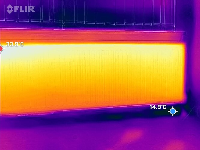
I can’t really make sense of your radiator pictures - could you take one from further away and maybe somehow mark the rad if it isn’t self-evident where it is?
They will be warmer at the top but definitely should not be cold at the bottom, especially when flow and return are so close together in temperature. Per se the 1K difference is not a problem and my first thought would be that flow rate is very high, so with the high volume of warm water coming in it can only cool down by 1K. However, as your radiators are not fully hot, another reason would be that the water is not properly distributed through the radiators - hence my request for a wide angle IR picture of your rads.
You could also try taking an IR video if your hardware supports it to record how the warm water distributes through the rad as it comes in, i.e. close the TRV, wait for the rad to cool then open it and record. A time series of images would also do the trick.
Hi Andre,
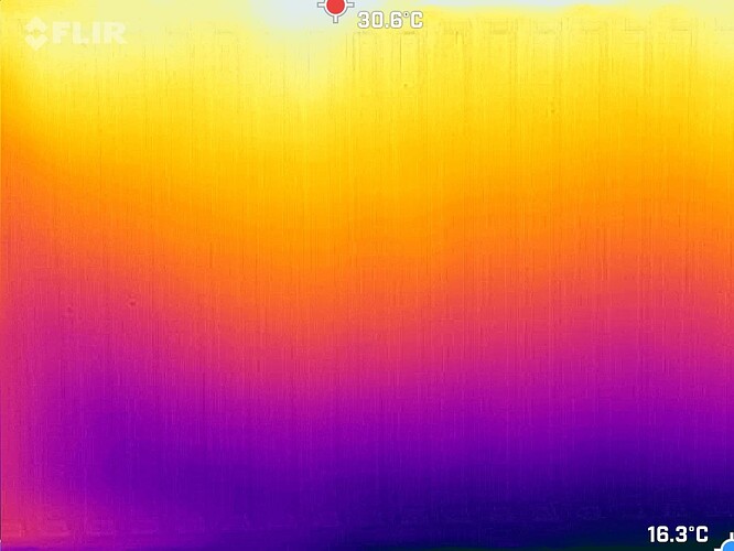
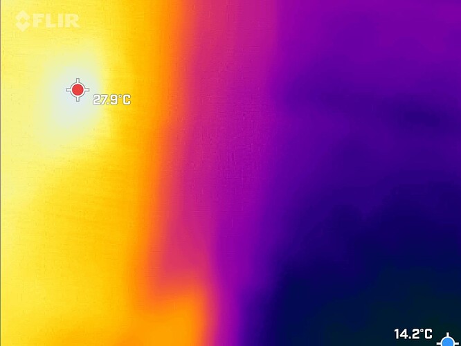
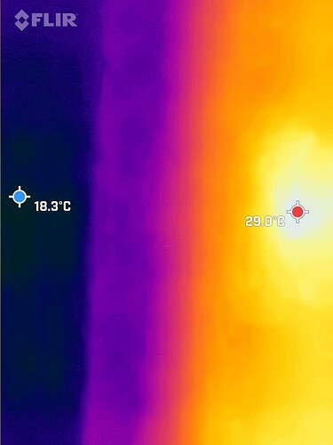
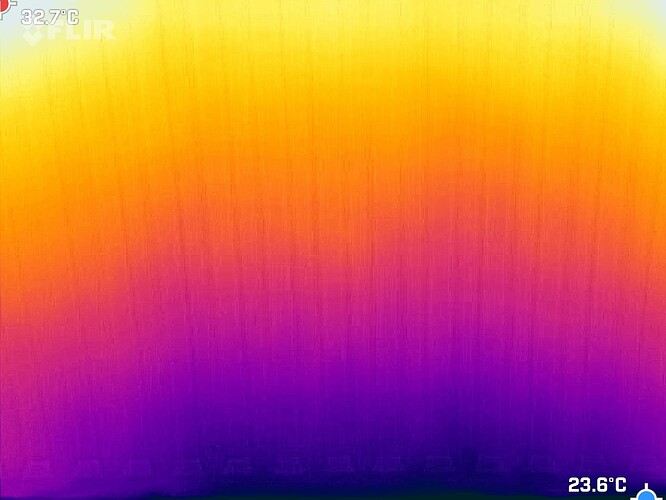
Took the close photo initially so the colour scale highlighted the cold bottom of the rad more clearly.
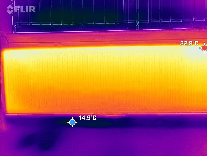
Attached are wide angle. Difference between the top and bottom of the rad is around 10+ degrees
Flow rates are as folk expected (question asked to the forum earlier)
I will have a bash at the time lapse photo and get back to you.
Those look quite ok to me to be honest. There is cooling to be expected from top to bottom as the water releases its heat energy into the room. And the warmer water will tend to flow towards the top. I think your measurements of the rad flow and return pipe might be inaccurate - just the heat conduction from the radiator will make it difficult to externally measure the temperature there. I think the radiator balancing might help - you probably need more flow to that big radiator so the temperature drop across it is only 5K and hence its average temperature a bit higher, leading to more heat output. However take this with a grain of salt, my radiators are attached to a UFH manifold and the balancing works differently there.
I won’t answer this directly as I agree with everything Andre has said.
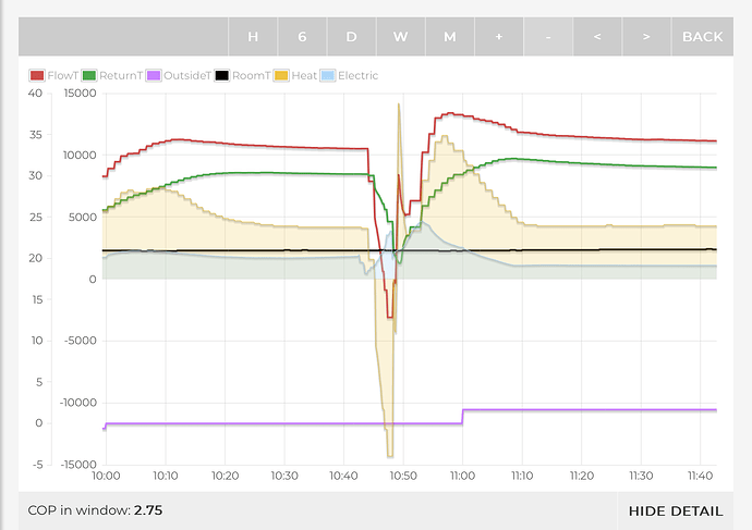
However with respect to your low COP; are you still running on Expanded modulation? I was running in this mode and was getting poor COP (2.5-3.0 ) after the outside temperature dropped to zero ish. I have since changed to Active room modulation and the COP has improved significantly (3.5-4.0) at the same temperature.
Also bear in mind that at this time of year your heat pump will carry out defrost cycles which will drop your COP considerably. These occur when the outside air is close to zero and damp. If the COP you are quoting cover several hours there may be some of these cycles within it.
Example of a defrost cycle shown below
Note: the negative heat and positive electric power leads to a negative COP over this period.
Hi @Kcf
In my opinion, the best way to “balance” the rads is to get each one as close to the same temperature as possible, in it’s midpoint.
So in the rad above, I assume your midpoint is around 33.4 deg. So if any are colder, then open their LOCKSHIELD VALVES by a half a turn and recheck in an hour.
If other rads are fully open, then reduce this one by a half a turn
Rince and repeat
Remember, TRV sides should be fully open
Hi Andre,
So a 10 degree difference between the top of the radiator and the bottom is normal? (Not a leading question, I have no idea/background knowledge but thought it would be closer than that.)
It’s difficult with heat cameras as the colour gradient goes from the lowest to the highest. This is why I go close up, so the full colour gradient is just for the rad, not the cooler surroundings.
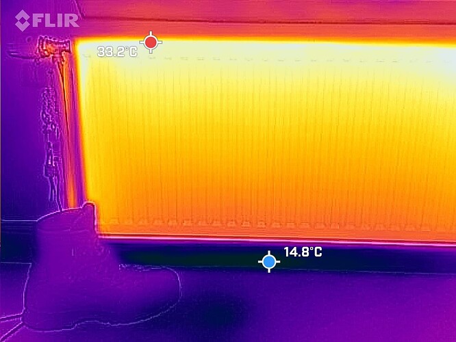
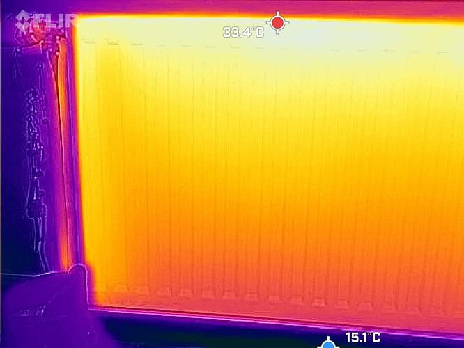
Couldn’t upload a video, so took 3 photos as I move in closer. First has a pair of boots hopefully showing that the height is only around 1.5 feet. For the last bit as I move in you can see that the top of the rad is around 32, the bottom around 23 Deg.
Is that normal and in fact the rad does not need a power flush? The temp difference is obvious even when just using your hand.
The 10°C difference across the radiator sounds rather large and suggests limited flow across this radiator.
My understanding was that your unit was a 5kW Arotherm which is running at 860 l/hr. This unit will modulate down to 2kW and up to 7kW.
When running at 2kW (using specific heat formula) the unit will increase the temperature of the water flowing through it by ~2°C. In a system where you are emitting all this heat through the radiators and all rooms are balanced, the temperature loss through each radiator will be ~2°C.
Why the difference between 10°C you’re seeing and this ~2°C? Several possibilities which boil down to restrictions to this radiator or excess flow stealing the flow elsewhere on your system.
The restriction to the radiator is not necessarily something which might be removed by flushing; it might be cause by long pipe runs to this radiator or valves shut in on the radiator.
Hope this provides some help?!
I would agree with @JimR . This to me just points to lower flow across the rad. If there was sludge buildup, the cold spot would be far more pronounced in the bottom.
So you need to open up the LOCKSHIELD VALVE a bit on this, or close others elsewhere on the circuit.
To absolutely prove the point, close all other TRV’s meaning that this is the only open rad on the system, and watch it heat fully (albeit ensuring the lockshield valve is decently open)
I have to say, the FLIR is the right job. I have one myself and I have used it more with my solar system and batteries, but has been invaluable for balancing.
I fully agree with @JimR and @championc - probably you have to increase flow to the radiator. However, probably the coldest rad temperature is not equal to what comes out the return. Also, youve got quite some cold spots below the radiator. The cold air from there could well cool down the rad more. It looks somewhat similar to what my fans under the radiators do - locally cool it down quite a bit.
Hi folks,
I closed off the trv’s in all the other rads and the temp differential on the rad reduced to 5 degrees.
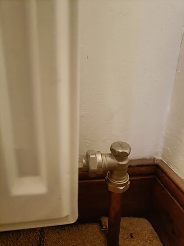
So thought to open the rads lock valve but none on the ground floor, including the problem rad seem to have one…
Do I assume by this that the ground floor rads are all wide open, so I have to restrict the rads in the first floor to increase the flow on the problem rad?
(I’ve moved this entire conversation into its own topic so it’s easier to follow)


