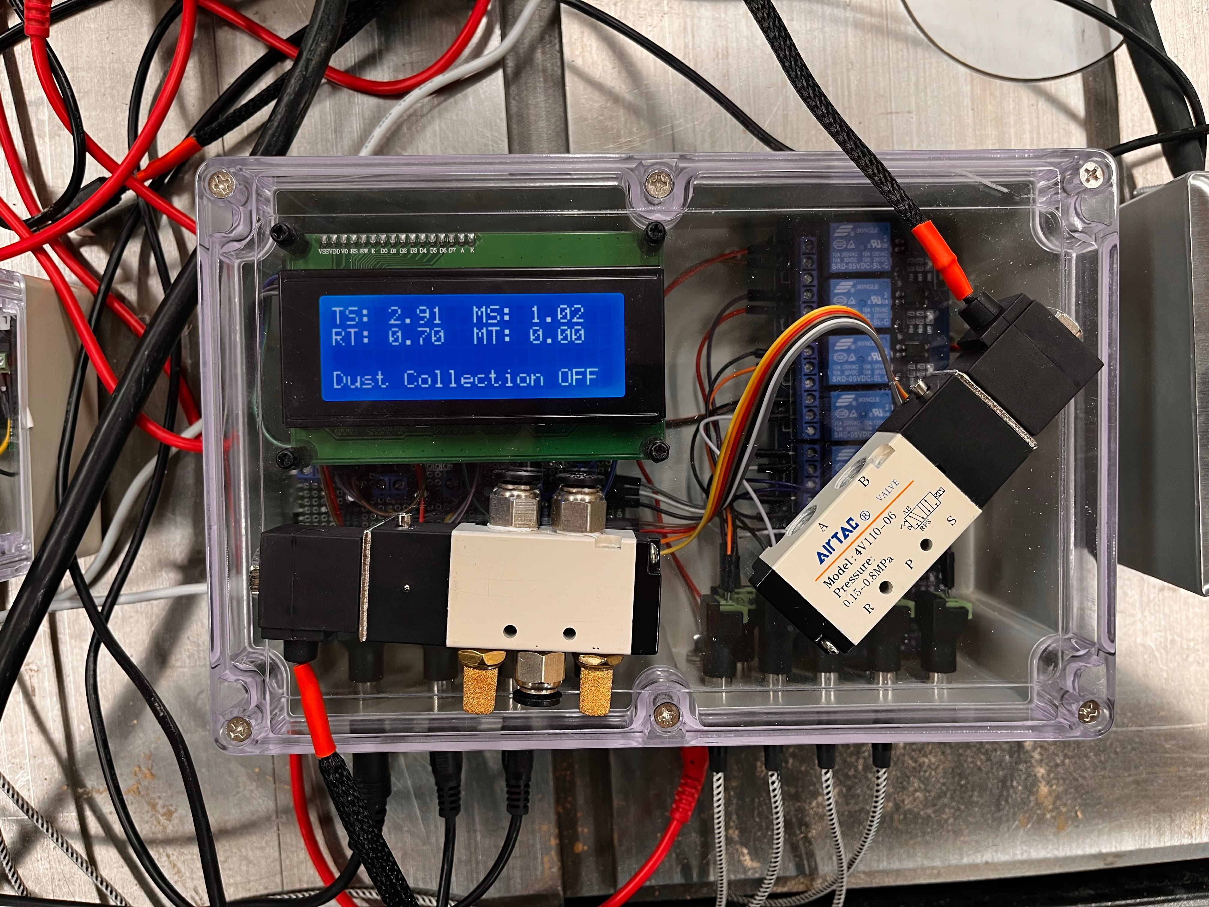
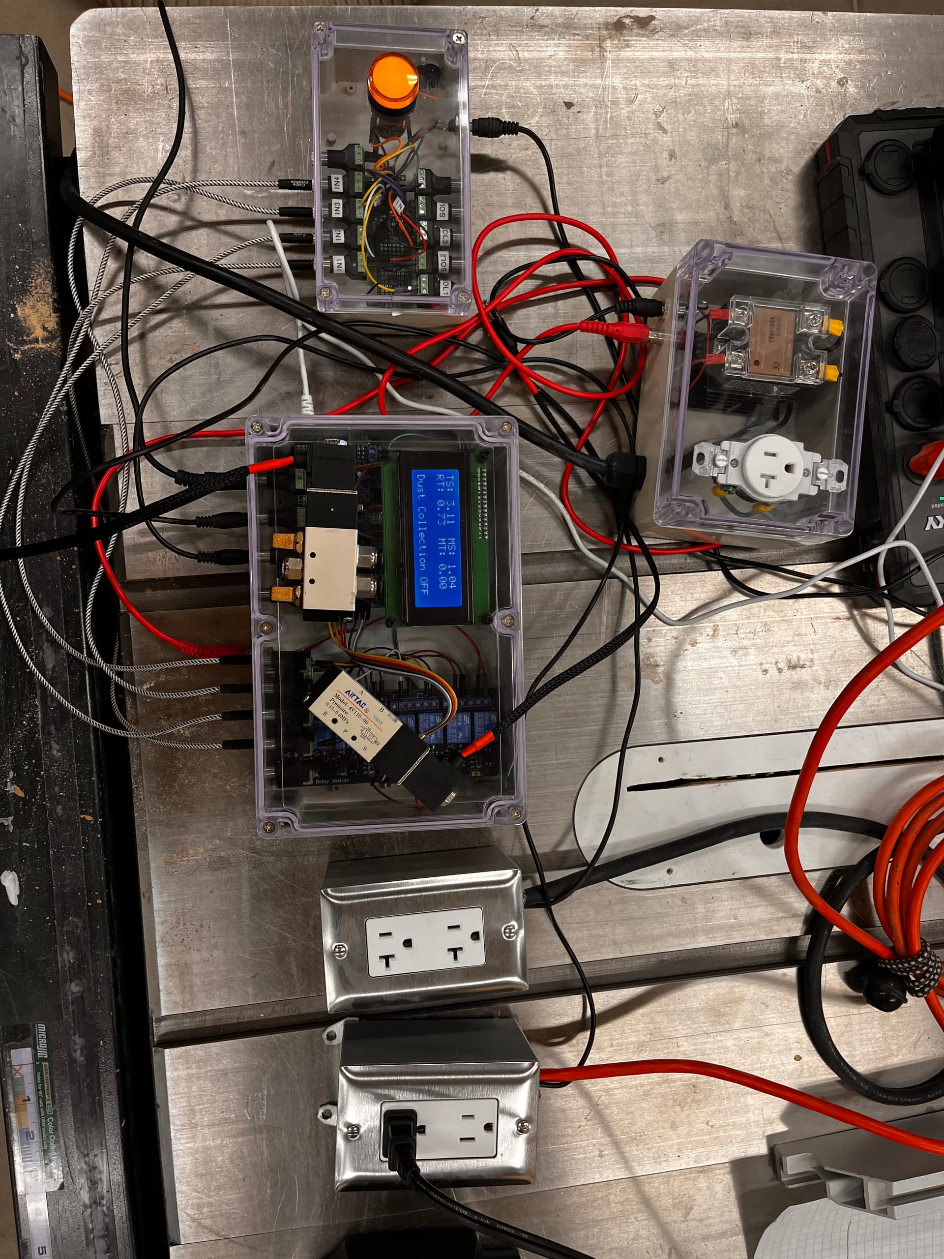
Looking for some guidance on a project. I’ve built a dust collection system using an Arduino Mega 2560, and some AC current sensors. For all intents and purposes, it is working as expected.
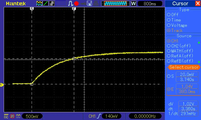
My plan is to keep the Arduino powered off when not in use. Each time I power on, the sensors are read and I see a value of approx. 138 for each of the four sensors and then they return to near zero.
I’ve set my IRMS values to min value of 150, so that the dust collector does not turn on until the set value for each piece of equipment is reached.
Regardless of the min. value set, for the ‘boot’ time of the Arduino, and the reading of the sensors, the dust collector will turn on and quickly off.
I’m looking for a way to prevent this short on/off cycle of the dust collector when I turn on the Arduino. Any help would be appreciated. I’m just an old guy with a shop, trying to learn some new stuff, so not really a programmer.
// Dust Collection System for Shop
#include <LiquidCrystal_I2C.h>
LiquidCrystal_I2C lcd(0x27,20,4); // set the LCD address to 0x27 for a 16 chars and 4 line display
/*********************************************************/
/* Program for Dust Collection System - Trent Badger's shop */
#include "EmonLib.h" // Include Emon Library
EnergyMonitor tool1, tool2, tool3, tool4; // Create instances - Table Saw, Miter Saw, CNC Router
const int dustCollectionRelayPin = 51; //Relay to Dust collector
const int blastGate1Pin = 27; // DC Leg 1 gate
const int blastGate2Pin = 35; // Table saw gate
const int blastGate3Pin = 39; // Miter Saw gate
const int blastGate4Pin = 43; // CNC Router gate
const int blastGate5Pin = 47; // Optional gate
void setup()
{
Serial.begin(9600);
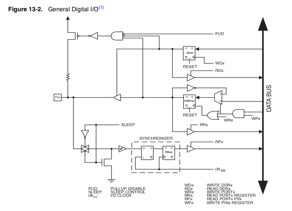
pinMode(dustCollectionRelayPin,INPUT_PULLUP);
pinMode(blastGate1Pin,INPUT_PULLUP);
pinMode(blastGate2Pin,INPUT_PULLUP);
pinMode(blastGate3Pin,INPUT_PULLUP);
pinMode(blastGate4Pin,INPUT_PULLUP);
pinMode(blastGate5Pin,INPUT_PULLUP);
pinMode(dustCollectionRelayPin,OUTPUT);
pinMode(blastGate1Pin,OUTPUT);
pinMode(blastGate2Pin,OUTPUT);
pinMode(blastGate3Pin,OUTPUT);
pinMode(blastGate4Pin,OUTPUT);
pinMode(blastGate5Pin,OUTPUT);
digitalWrite(dustCollectionRelayPin,HIGH); // enable off
digitalWrite(blastGate1Pin,HIGH); // enable off
digitalWrite(blastGate2Pin,HIGH); // enable off
digitalWrite(blastGate3Pin,HIGH); // enable off
digitalWrite(blastGate4Pin,HIGH); // enable off
digitalWrite(blastGate5Pin,HIGH); // enable off
double Irms1 = 0;
double Irms2 = 0;
double Irms3 = 0;
double Irms4 = 0;
lcd.init(); //initialize the lcd
lcd.backlight(); //open the backlight
lcd.clear();
lcd.setCursor(0,0); // set cursor to column 0, row 0 (the first row)
lcd.print("DC X");
lcd.setCursor(0,1);
lcd.print("ShopTool Monitor");
delay(4000);
tool1.current(0, 111.1); // Current: input pin, calibration for table saw
tool2.current(1, 111.1); // Current: input pin, calibration for miter saw
tool3.current(2, 111.1); // Current: input pin, calibration for cnc router
tool4.current(3, 111.1); // Current: input pin, calibration for cnc router
}
void loop()
{
double Irms1 = tool1.calcIrms(1480); // Calculate Irms only
double Irms2 = tool2.calcIrms(1480); // Calculate Irms only
double Irms3 = tool3.calcIrms(1480); // Calculate Irms only
double Irms4 = tool4.calcIrms(1480); // Calculate Irms only
lcd.clear();
lcd.setCursor(0,3);
lcd.print ("Dust Collection OFF");
lcd.setCursor (0,0);
lcd.print("TS: ");
lcd.setCursor (4,0);
lcd.print(Irms1);
lcd.setCursor (10,0);
lcd.print("MS: ");
lcd.setCursor (14,0);
lcd.print(Irms2);
lcd.setCursor (0,1);
lcd.print("RT: ");
lcd.setCursor (4,1);
lcd.print(Irms3);
lcd.setCursor (10,1);
lcd.print("MT: ");
lcd.setCursor (14,1);
lcd.print(Irms4);
if (Irms1 > 250) { //set to range on startup of table saw ~250
digitalWrite(blastGate1Pin,LOW); // enable on
digitalWrite(blastGate2Pin,LOW); // enable on
clearRow(3);
lcd.setCursor(0,3);
lcd.print ("Table Saw (IRMS1)");
delay(2000);
dustOn();
} else
if (Irms2 > 150) { //set to range on startup of CNC Spindle ~150
digitalWrite(blastGate1Pin,LOW); // enable on
digitalWrite(blastGate3Pin,LOW); // enable on
clearRow(3);
lcd.setCursor(0,3);
lcd.print ("DC ON IMRS2 ");
delay(2000);
dustOn();
} else
if (Irms3 > 150) { //set to range greater than 138 on startup of controller ~150
digitalWrite(blastGate4Pin,LOW); // enable on
clearRow(3);
lcd.setCursor(0,3);
lcd.print ("DC ON IRMS3 ");
delay(2000);
dustOn();
} else
if (Irms4 > 150) { //set to range greater than 138 on startup of controller ~150
digitalWrite(blastGate5Pin,LOW); // enable on
lcd.setCursor(0,3);
clearRow(3);
lcd.print ("DC ON IRMS4 ");
delay(2000);
dustOn();
} else {
dustOff();
delay(2000);
digitalWrite(blastGate1Pin,HIGH); // enable off
digitalWrite(blastGate2Pin,HIGH); // enable off
digitalWrite(blastGate3Pin,HIGH); // enable off
digitalWrite(blastGate4Pin,HIGH); // enable off
digitalWrite(blastGate5Pin,HIGH); // enable off
}
}
void dustOn()
{
digitalWrite(dustCollectionRelayPin,LOW); // enable on
}
void dustOff()
{
digitalWrite(dustCollectionRelayPin,HIGH); // enable off
}
void clearRow(byte rowToClear)
{
lcd.setCursor(0, rowToClear);
lcd.print(" ");
}