For discussions related to emonPi, emonTx, emonBase and emonGLCD hardware and Arduino firmware
Hi all,
This is my first post here…
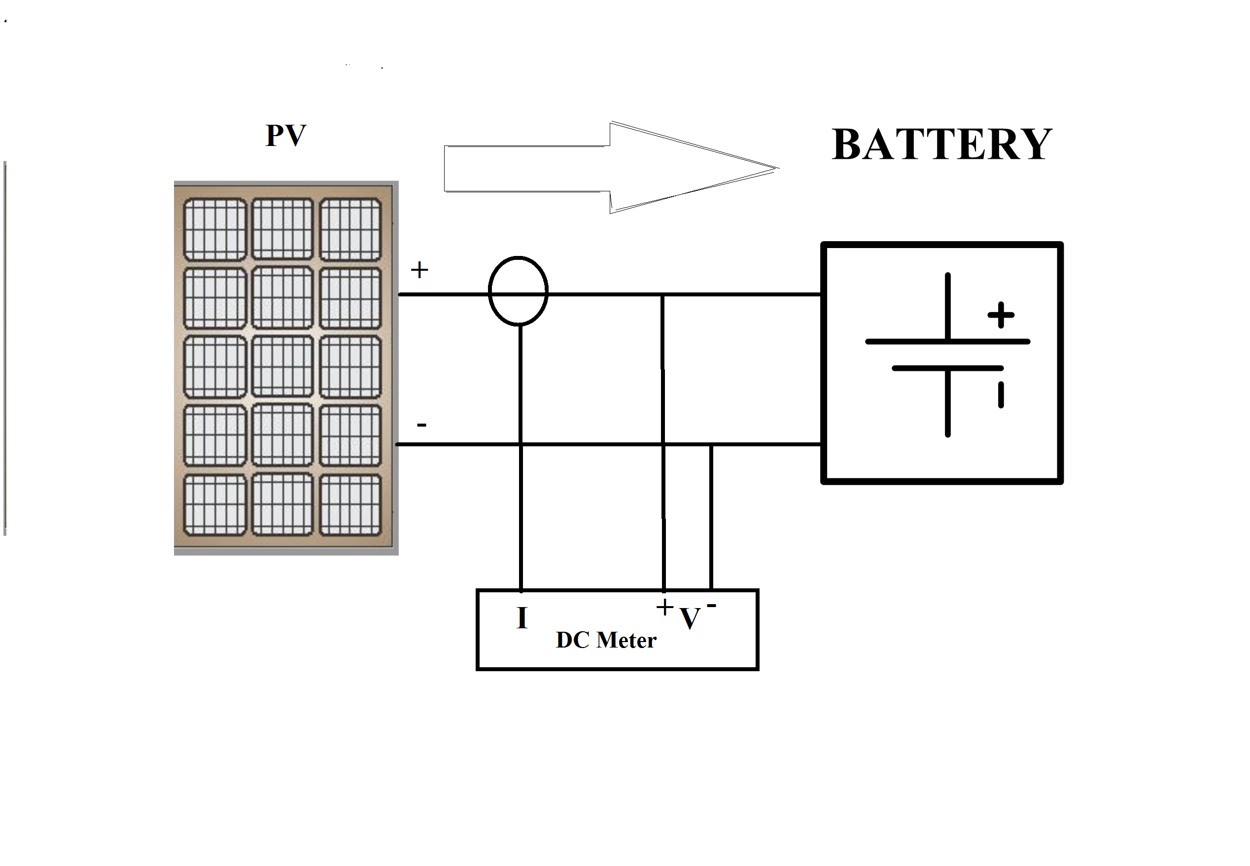
I want to connect a dc meter between my solar panel and battery for measuring and logging PV generated output . Also i am thinking to connect another meter after the battery to measure outgoing power. My questions are:
Are there any feasible and cheap solutions to make certain circuit based on Voltage/current hall sensors with MCU’s to log PV generated data ? what could be the method to store analog data coming from sensors to store in the memory and take output as a csv file.
Any cheap product (dc meters) available in the market for dc parameter measuring and data logging. (at least for 2 months).
personally i have not come across any cheap DC ct they always being a bit price - your most likely going to have to use an in-line one. Something like this:
and these:
You have to make your own voltage sensor by using a couple of resistors.
To the best of my knowledge - no to both. The problem is, for safety you must isolate the measurements end from the rest of the world.
That is easy with current - you can have a Hall effect sensor that picks up the magnetic field surrounding one of the cables. Even it you have to break into the cable, it will still give you galvanic isolation.
But you cannot easily do that with voltage. Hall effect sensors require too much current for the arrangement similar to that you would use with a moving coil meter - a multiplier resistor to turn the voltage into a current.
The only realistic way that I know of - and unless you are skilled and competent to work on live d.c. systems at whatever voltage yours is, I don’t recommend you try - would be to use a direct connection for voltage, a Hall effect transducer for current, feed those measurements into an Arduino powered from the system. The only connection to the outside world must be by radio. You must realise that there is great danger when you are getting such a system to work, both to yourself and to any computer or other equipment that you use. You cannot connect anything else, even for debugging and testing, unless it is battery powered and isolated and you know exactly what the dangers are.
You can buy isolating voltage sensors, and they have been used here before (look and search here under “Archived”) but they don’t satisfy your requirement to be “cheap”.
There is no such thing as a d.c. c.t. No transformer will work on direct current, a transformer works on the rate of change of flux, if the primary current is not continually changing, therefore the flux is not continually changing, there will be neither secondary voltage nor current, so it does not work.
A Hall effect device is NOT a current transformer.
@tailchopper DO NOT follow Stephen’s advice about just adding resistors. He clearly does not understand the importance of galvanic isolation, nor the dangers of ignoring the need for it. I don’t know what his experience or qualifications in electrical engineering are, you can check mine in my profile.
I assumed that detail was omitted for the purpose of illustration. If there is, is the charger / inverter capable of giving the required information, either via IR, Bluetooth or on a data bus?
if he just monitoring a battery system which is generally 48 volt then i do not see the problem if he wants to monitor a individual solar panel that voltage in a basic solar panel is 22 - 72 volts at open circuit generally 10 amps or less solar … he never said he was using a string inverter where voltage is 500 volts or higher…
sure there are "non invasive DC current sensors’ I have one they measure the magnetic field. the one I have you place a place separate positive and negative wire in slot and when the current it creates a small charge/
here are example of other DC hall effect dc Current sensors ( but they are pricey even on alibaba at usually +100 each ) http://www.cy-sensors.com/CYHCS-OL-RW1.htm
here is another one on a single wire used by an avionics company . http://www.vansairforce.com/community/showthread.php?t=63341
I just never found one sold for arduino yet
CT as an acronym is really non specific can be used to describe a Current Transformer or Current Transducer depending on how nit picky a person might be
and here a simple circuit for measuring higher voltage DC with an analog optic coupler
using either HCNR200 ( with voltage divider) or IL300
It may well be that in your line of business, you commonly refer to both current transformers and current transducers as c.t’s. However, in my half-century or so in electrical engineering, I’ve never heard the term c.t. applied to anything other than a pure current transformer. Maybe this is in part because, although the Hall effect was discovered in the 19th century, practical devices using it only became widely available at the end of the 20th century, and by that time the term c.t. was very well established as an abbreviation for current transformer.
So as not to confuse those who are less technical than you and I, and who may be unfamiliar with this area, I think it would be a good idea to keep to the practice on this site of reserving “c.t.” for a true current transformer, and when you mean anything else, write out in full “current transducer”.
I draw this diagram just for explaining purpose. There is actually MPPT converter in between PV and battery and an Inverter after the battery which is connected to the grid.
Robert you are right, there is a MPPT converter in between. Also there is an AC meter at the grid side. DC-AC Inverter can be connected for data logging but for now i want to measure how much PV is generating. Later i can do it in combination, such as measuring inverter efficiency or dc-dc converter efficiency.
I have used some expensive current transducers LV-25P and LAH-25P in an inverter board which was connected to a DSP controller (TMS320F28335). However that was a funded project and i had a lot of stuff to order or replace. Currently i am doing this in a domestic PV system so searching for some cheaper option.
Here is one solution i thought might be possible. But i needed your expert advice on this.
two separate external ADCs of 12 or 16 bits (depending upon resolution).
One shunt resistance that can be suitable for upto 10 Amps.
Two similar VDR circuits with multiple resistance to convert more than 600V (like for say 650 or 700 V) to 5V for ADC measurements.
Using microcontroller for reading ADC values, 1st ADC1 value will be voltage, Current will calculate from difference of two ADCs (ADC1-ADC2)/R as V=IxR and I=V/R,
and Power will be simply P=VxI.
Using a character LCD for display (optional)
Using serial communication for logging to system or I2C EEPROM or SDCARD for data logging
no worries tailchopper, strings system are not my flavour for solar systems. i prefer micro grid ties-- as one can easily monitor the individual solar panel and inverters , more efficient then string, much safer and last basically forever…
where as with string you can not, is not and does not . the only advantage of a string it is slightly cheaper up front cost
As I wrote very early on, you need to respect the fact that the d.c. system doesn’t have to be referenced to ground/earth, so everything needs to be galvanically isolated at some point, the closer to the d.c. loop, the better (from the point of view of your safety when working on the system). And remember that 500 V d.c. can be lethal.
Depending on the max. input voltage of your chosen ADC, the 10 A shunt could be an embarrassment. I don’t think it’s realistic to calculate the current from the difference between two voltages. Have you considered the stability of the dropper resistors? If your shunt is (say) 200 mV @ 10 A, then for 5% accuracy in the current, you need 5% stability in the difference between the two voltages, i.e. the two need to stable to within 5% of 200 mV in 500 V. That’s a tall order. Any standing inaccuracy can be calibrated out in the maths, but stability can’t be. You need to measure the voltage directly, or find another way.
I think a Hall effect device in place of the shunt would be a better approach. Typically, a Hall effect device will give isolation and around 2% accuracy or better.
If you’re OK with the requirements for creepage distances etc at 500 - 700 V, then the “linearised” opto-isolator (the Vishay IL300 that Stephen mentioned) in the circuit in the application note would give you isolation and more than adequate linearity, but to maintain isolation, the servo op.amp on the high voltage (input) side needs either its own isolated power supply, or to take its power from the d.c. loop, which complicates the design. That must be totally separate from the power supply for the low-voltage side.
Having got your safely isolated and low voltage signals, then the rest is comparatively easy - you can quite safely work on the ADCs and processor, plug in whatever you need to extract the data, live or from the logs, and generally do as you would with an Arduino or emonTx on the bench.
[Caution: the Hackaday link contains some very wrong “facts”, so beware.]