Well: I don’t think there is a “dramatic” effect on efficiency (my monitoring software computes %COP impact according to current LWT and OAT for LWT lifts of 1,2,3,and 4C), but it certainly DOES have an effect and I really don’t see why I should accept a systematic inefficiency when well-implemented buffers are feasible.
The more noticeable effect of the issues I describe is that the heat pump return water is hotter than it should be - ie rather warmer than the rad RWT - so the HP struggles to maintain its dT and so cycles. I don’t see why I should accept an unstable system.
NAPIT enginners seem to agree that I should not have to accept these!
My simulations stronly suggest that a mild weather flow of 28C should be perfectly within the modulation range, given the emitters in place.
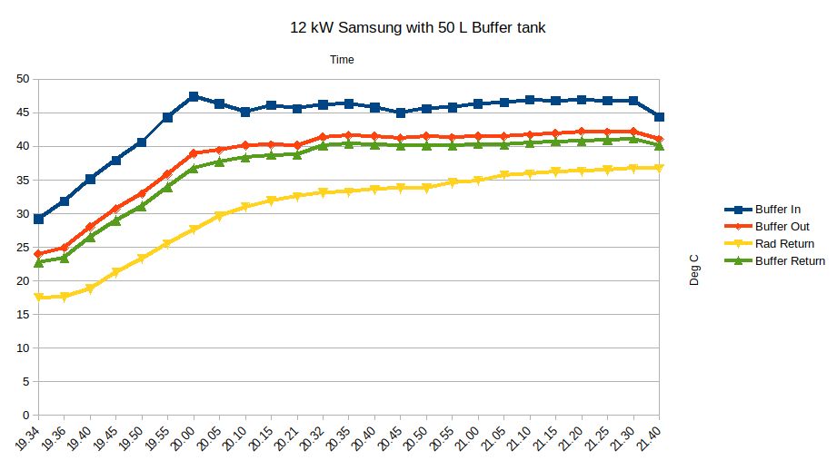
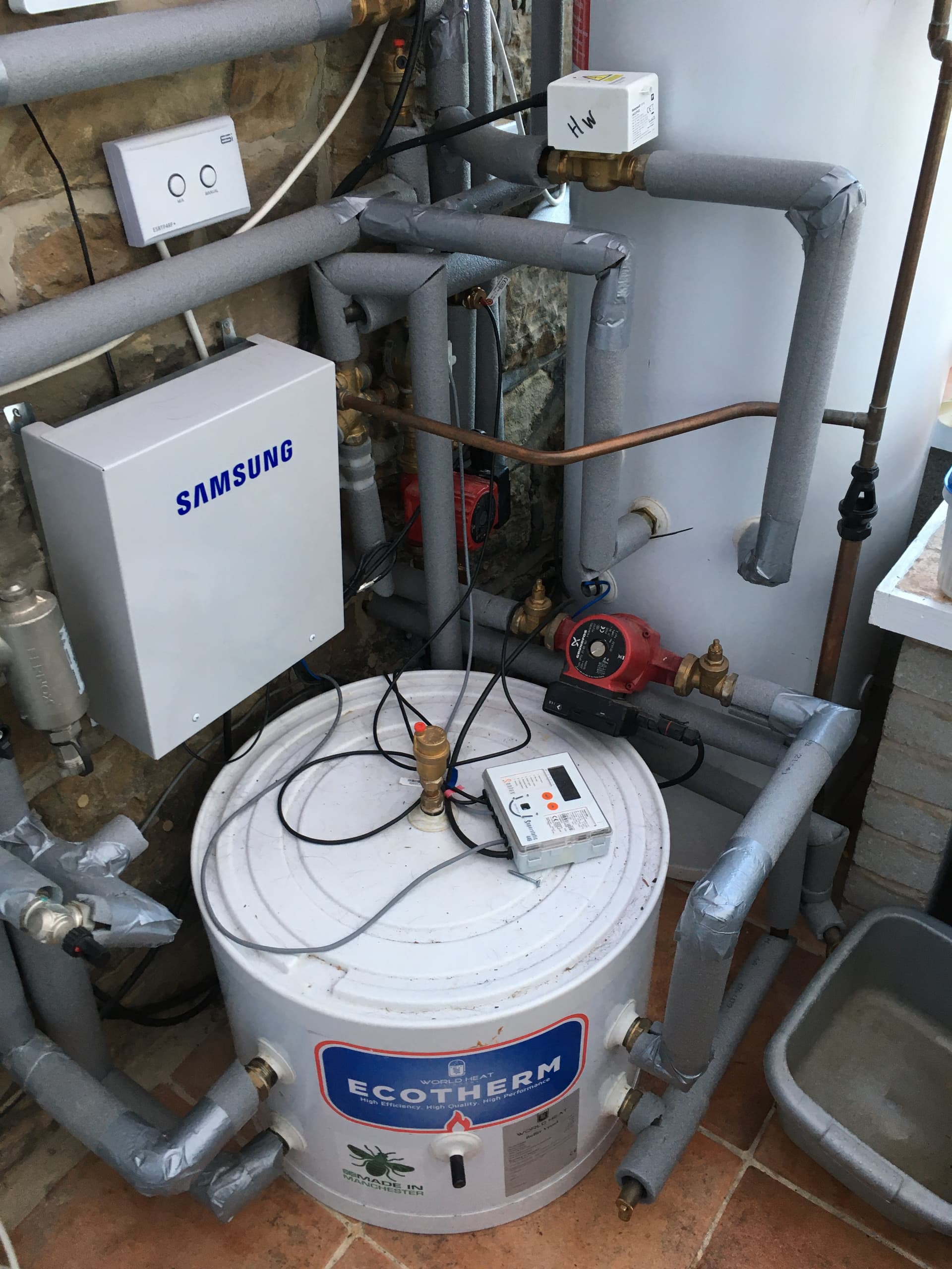
Hi Adam, I missed your original post, but I thought I would share my experience of a World Heat 50L buffer tank. I had the same experience as you. The tank is so squat that the distance between the pipes of 2-3 inches means that mixing of flows is inevitable. My graph is labelled differently to yours with Buffer In meaning flow from ASHP to the buffer and Buffer out meaning the flow to the radiators, but I think it is very similar and I was losing 4-5 degC between what was being delivered from the ASHP to the buffer and what was going to the radiators. I had it removed, but it was quite expensive.
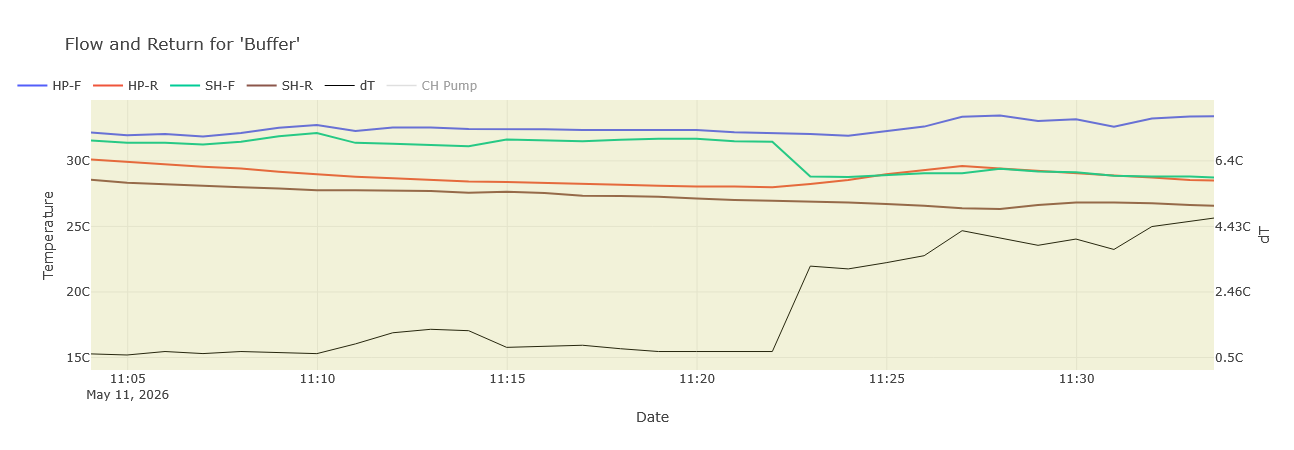
Update: I finally got EDF Heat Pumps to replumb as a 3 pipe arrangement and the difference is dramatic (and there were no pressure-related faults, which was the usual objection from installers to making this change). Specifically: the re-plumbing included valves to allow for switching between 3- and 4- pipe configurations.
I switched from 3- to 4- pipe arrangements at about 11:22.
The dT is the difference between the HP flow and space heating (SH) flow, ie the key blending loss metric.
The small hump in dT between 11:10 and 11:15 is due to the HP pump slowing right down such that the secondary pump was drawing cooler buffer water into the space heating flow, and me then dropping the secondary pump speed a little to counter-act that; I have not yet optimised the secondary pump speed.
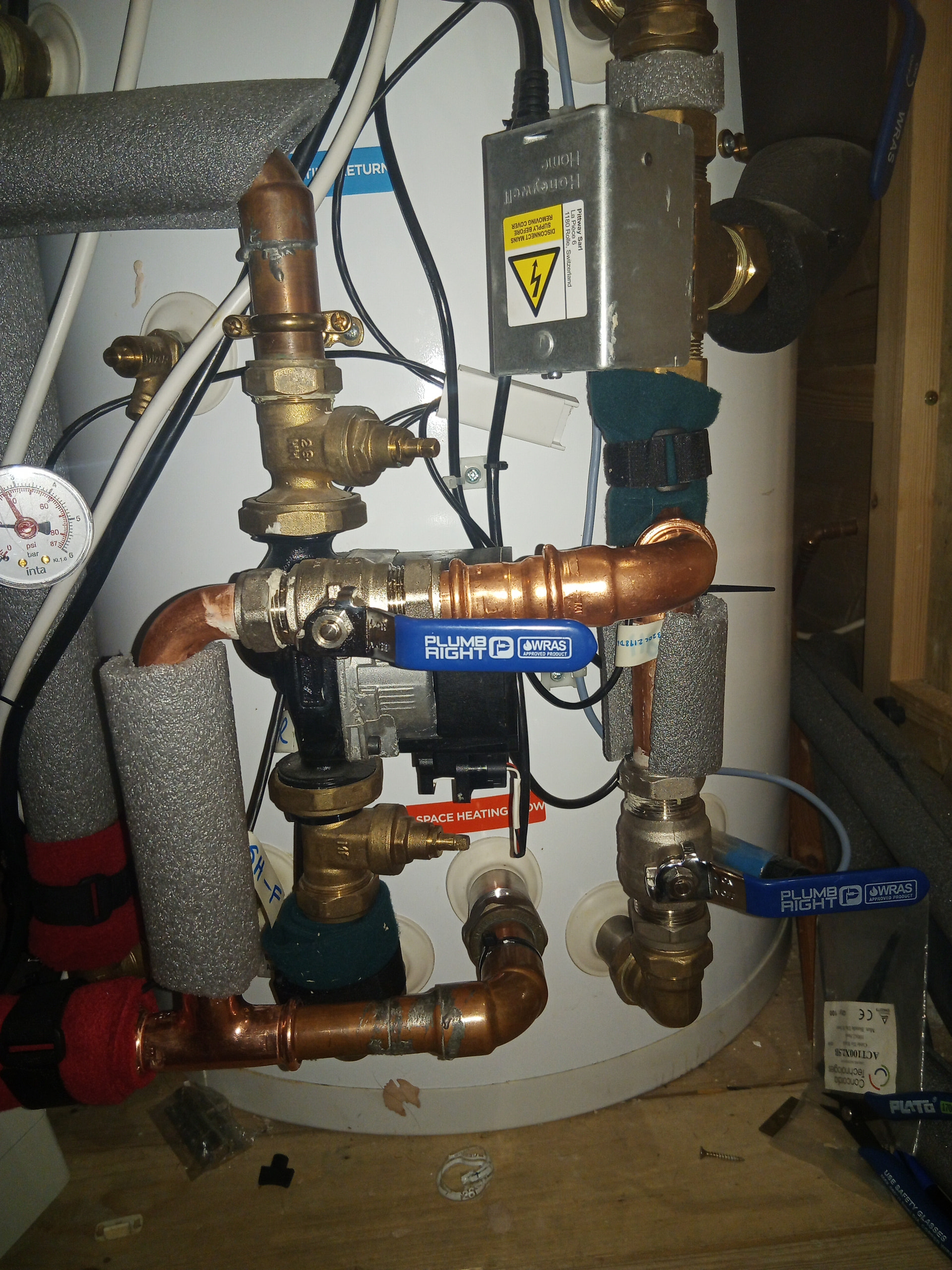
For clarity, here is the plumbing. HP flow comes in top right (motorised valve controls DHW vs space heating).
The configuration shown has the bottom left blue-handled valve closed and the one in the centre open - ie the 3 port arrangement - so that HP water can flow directly to the space heating flow, which is bottom left. Temperature sensors are wrapped in red or green fleece. I think the sensor on the space heating flow should be further away as it seems to read low in the pictured position, presumably due to heat loss through the pipe back to the cooler buffer water. Sensor readings ~30cm further downstream are closer to the HP flow temp.