Daikin Pre-plumbed Cylinder (WorldHeat) Buffer Strangeness

I have been looking at the water flow and return temperatures on the 4-pipe buffer which forms part of the Manchester-made WorldHeat pre-plumbed cylinder which is installed with a Daikin EDLA. Something is quite wrong so I am seeking other people with the same hardware to “compare notes” with a view to finding out whether there is something wrong with the install, manufacture of my tank, or the fundamental buffer design in these units.

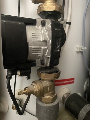
The buffer appears to be plumbed in correctly. Reading from left to right around the base, where the pipes exit, the order is Heat Source Return, Space Heating Return, Space Heating Flow, Heat Pump Flow. This matches the picture in the installation manual. The body of the secondary circulation pump has an arrow cast into it showing flow is indeed into the SH return. When I got the cylinder, however, the pump was on back-to-front (pumping water out of the SH return pipe!) but I spotted this and got the installer to reverse it.

The issue is that, having monitored the water temperatures (from the outside using DS18B20 devices cable-tied to the pipe, with some thermal paste and surrounded by several turns of fleece fabric for insulation), I can see the water which leaves the SH flow is the same temperature as the HP return. A typical approximate reading for “heating on” would be HP flow 32C, HP return and SH flow 28C, SH return 25C. This is clearly BAD; I’m paying a COP penalty for heating the water to 32C whereas heating to 28C would be sufficient for the same space heating, given an ideal buffer tank. This situation persists for a range of pump speeds (my original plan was to monitor the temperatures so that I could modulate the secondary pump to properly balance the buffer tank).

It looks like either the HP or SH pipes are transposed.

SO… I am looking for evidence:
A. Does my arrangement of 4 pipes exiting the buffer match yours?
B. Which direction is your secondary (space heating) circulation pump (arrow on metal body)?
C. Do you have any temperature readings? All 4 pipes at the buffer would be best (either using a similar sensor setup to me, or maybe an infra-red remote temp meter would do). Alternatively, do you have evidence that the space heating flow temperature is close to, or far from, the leaving water temperature reported by the heat pump?

In spite of this issue, the heat pump appears to be behaving itself, with longish periods of steady energy input (SMD120 feeding my Open Energy Monitor). Its attempt to maintain its flow-return dT is, of course, unhelpfully suppressing my emitter temperature!

Thanks in advance, Adam
Not sure about the design but I changed my 4 pipe buffer into a three pipe one - videos and text out there - improved performance no end.

Hi Adam.

I don’t have the WorldHeat buffer like yours, just a simple vertical 4-nozzle 50 litre buffer tank that my installer chose (heat pump in/out and emitter out/in connections with a secondary fixed-speed pump on the emitter circuit).

I installed decent quality surface T/Cs on the four inlet/outlet lines (with ht cement and plenty of insulation) some time ago, and more recently I had a Sontex 389 heat meter installed on the emitter side of the buffer tank, so I could see what energy was actually entering the house (as opposed the the heat supposedly leaving the Outdoor Unit). I had to have a Sontex because I run on 20% glycol, so the heat meter can to be calibrated accordingly.

I found the following in a recent test run:

  1. Temperatures into/out of the buffer tank fluctuate fairly rapidly as the various control parameters (HP controller outputs, TRV positions) take effect, so it’s not that easy to get steady state readings.
  2. My surface T/Cs gave outputs fairly consistent with the (nearby) heat meter T/C outputs (within ~1degC), and with the LWT and RWT reported temperatures (though there was a consistent ~1degC difference with LWT which I put down to either real temperature loss or T/C inaccuracy).
  3. Once the system was running reasonably steadily, the heat duty I calculated leaving the heat pump (from M.Cp.deltaT) was close to (with 5%) the heat duty I calculated passing the heat meter (and reported by it :slightly_smiling_face:).
    So in answer to your specific questions:
    A. Yes, by the sound of it.
    B. I’m sure that my secondary pump has been installed correctly!
    C. Typical temperature readings (once stable): T1 (ex HP) 48.9degC, T2 (to HP) 46.7degC, t1 (to emitters) 48.7degC, t2 (ex emitters) 42.8degC. My secondary flow is about 40% of the primary flow, so the deltaT (2.2degC primary, 5.9degC secondary) is fairly consistent.

So yes, the secondary flow (t1) should be reasonably close to your LWT (T1) but you should expect up to 1degC heat loss (LWT to buffer) on a cold day, depending on how much exposed piping you have and how well it is insulated.

(I realise that my secondary flow is not optimum - you should aim for primary and secondary buffer tank flows (thus deltaTs) to be about equal - but I’m still working on that particular case… :thinking:).

To summarise, I suspect that your perceived problems are less than your actual problems (at least with your buffer tank…).

Sarah

So, a picture is worth…
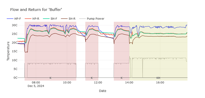
This is todays running. I think the legend is fairly self-explanatory but note that the background colour shows calling for heat, and the green-ish yellow area has a 2nd zone in play. “Pump Power” is the feedback signal from the secondary circulation pump (which is a UPM3 with nice PWM input for speed control and output of power consumption).

The space heating flow (SH-F) and heat pump return (HP-R) really are incredibly close! I think the periods when the pump is off are quite instructive. For example between ~12:30 and 13:00: a) the HP-F temperature (which is monitored very close to the cylinder) falls to the same value as the SH-R; b) the SP-F is highest. I interpret this as showing that the SH-F is at the top of the tank, while the HP-F is at the bottom. From about 12:30 it has established stable stratification.

During the period from 12:00 to 13:00, power consumption is only the HP quiescent 10W. Also, during this period, motorised valves are closed, so there should be negligable convective “turn-over” on the space heating side (I think this is evidenced by the gentle cooling curves for SH-F and SH-R during this period).

I cannot think of an alternative explanation than: the HP flow and return are connected to the wrong ports of the buffer.

I interpret the larger difference between HP-F and SH-F when both zones are an as being due to a larger volume of cool SH-R water entering the buffer and mixing with HP-F, while the HP flow rate remains roughly unchanged (or at least proportionally less changed)

1 Like

Thanks Sarah -
That T1-t1 difference is much more acceptable!

My aim was, as you note, to get balanced flows in primary and seconday by modulating the pump speed. Even if this comes down to some crude “rules” based on observation, as opposed to a fancy sensor-driven control loop, it would surely be an improvement. Getting the temperatures on each pipe was supposed to be the first step, and not the opening of a can of worms.

I have the Daikin r32 tank with a Daikin 9kw pump, what ever I do I can’t get a descent scop ( heating 2.8 ) playing with the secondary pump seems to make no difference. I watched a discussion on YouTube complaining that Buffer tanks are fitted by installers for ease of installation but can take 50% off efficiency! The tank can also be used as a volumiser in stead of a buffer tank, I was wondering if this would improve the efficiency?

@JohnC in spite of the issue which I describe above, I have been able to get COPs of just under 4 for the last several days, and looking at the un-averaged COP I see it is quite close to the values which the Daikin data book gives.
So, although some people are able to “fix” low CoP by converting to a volumiser or 3 pipe buffer, I consider that the vogue for buffer bashing is not well founded. Rather: buffers do not fix all design/implementation faults…

That said, the 3 pipe buffer plan does seem to have a nice theoretical case in its favour.

Assuming you’ve already tried the strategy of reducing the leaving water temp right down (mine is currently 32C for an outside temp of 4C and room temp of 17C, but the actual temp in the rads is only 30C due to the problem above) and running the system near-continuous during the day, I suspect your problem is probably due to too small a temp drop between the HP flow and return water and it I were you I’d investigate that. You can see this “live” in the MMI if you don’t have the OEM kit or an ESPAltherma.

BTW: do you also have the WorldHeat tank (not sure whether R32 indicates this or not).

1 Like

Badged as Daikin but has world heat sticker on it. MMI sensors suggest difference in heat pump return temperature and flow temperature is usually 3-4 degrees and flow rate is 10-11 lt/s problem is it’s using 1.5-2 kw at 4c. (W/c at 4c would be 39c) house set to 21c on madoka ( is actually only 20c )

Well… that dT and flow (assuming it is actually litres/min) look reasonable and I’ve had decent COP with similar.

I suppose one thing to consider is whether the data is good.

Just had Daikin round for first service! Guess what refrigerant leak! Hopefully next week re-charge and start process of tuning WC again. No wonder what ever I did made no difference. Be interesting to see what difference it makes to the scop. The engineer thought it should make a massive difference!

2 Likes

Adam I’ve just checked the arrow position on the secondary pump, it is in a downward position which to me would indicate a flow going into the tank rather than coming out!?

Is the arrow pointing towards the space heating return port of the buffer? In which case, the pump is the right way around. In terms of the circulation, it doesn’t matter where the pump is placed in the circuit, so long as it makes water move from the “flow” port to the “return” port.

1 Like

Indeed it should make a difference, and the poor COP with what seemed like OK dT and flow is explained by this. There is a refrigerant pressure sensor in the unit, and it is possible to get a reading from it using ESPAltherma, but it would have been good engineering if Daikin reported low refrigerant pressure as an error condition via the MMI.

1 Like

As a matter of interest the Daikin engineer found I only had 1.2 kg of refrigerant, should had have 3.6kg, the pump now runs a lot quieter, at least 50% more efficient ( cop now 3.5 and the weathers been cold ) and I can now play with the WC now which should hopefully make some difference. Before what ever I did made no difference! I’ve had this leak from new which has progressively got worse! My hot water cop was 1.3, yesterday it achieved 3.0. When I complained they told me it was working fine. This obviously came from the factory like this, one fitting was not tightened up enough. I wonder how many other people with poor performing systems this could apply to! Happy days now!

3 Likes

Is Daikin going to compensate you for the addational running costs due to their fault?