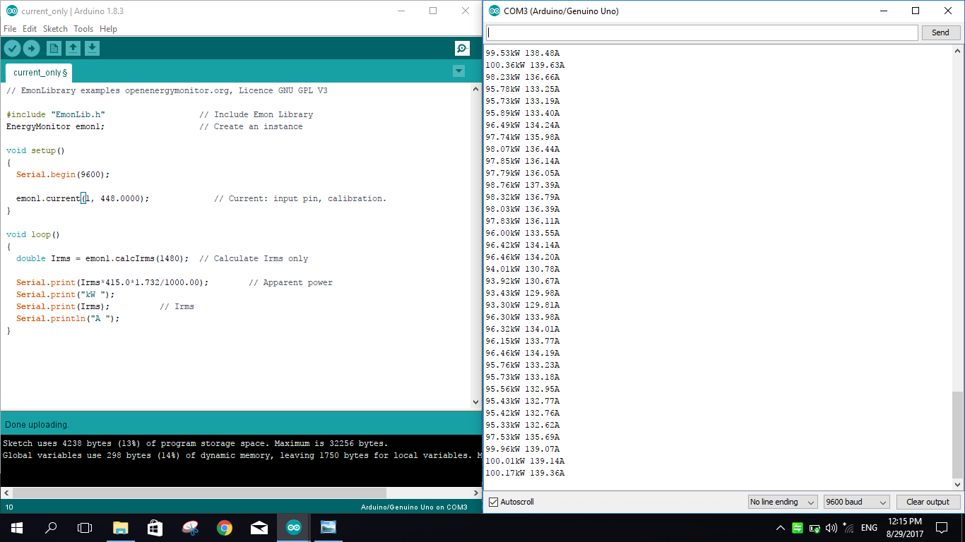
I am developing a large current monitoring system with SD card logging function.
The CT is 900A/300mA, which is 3000 coil turns. I use Arduino UNO R3 and utilise the Emonlib “Current Only” arduino code. The burden resistor I use is 5.6 ohm. I pretty sure that the calibration value is correct (3000/5.6ohm=535.71). However after the verification, I found the measure current is not correct(way far higher).
So my question is, whether a 900A/300mA CT is applicable to the Emonlib code? If yes, is that anything would cause the wrong accuracy?
Thank you all! Please request any info that you think can help u understand my condition. I have been trying so hard to trial and error.
There is no restriction at all in emonLib, apart from the usual rounding errors. The calibration factor is the actual current that gives you 1 V at the ADC input, so your calibration looks correct. But what are you using for the voltage reference in the calculation? If you have looked at the emonTx sketch and set #define emonTxV3, then it will be using 3.3 V as the reference, not 5 V, so your reading will be 51% high.
If that is not the problem, tell me the true current and what your Arduino reads, over a range of values. Saying “way far higher” doesn’t tell me where to start looking, whereas knowing the ratio should help.
I am using 5V as voltage reference, therefore I did not set the #define emonTxV3.
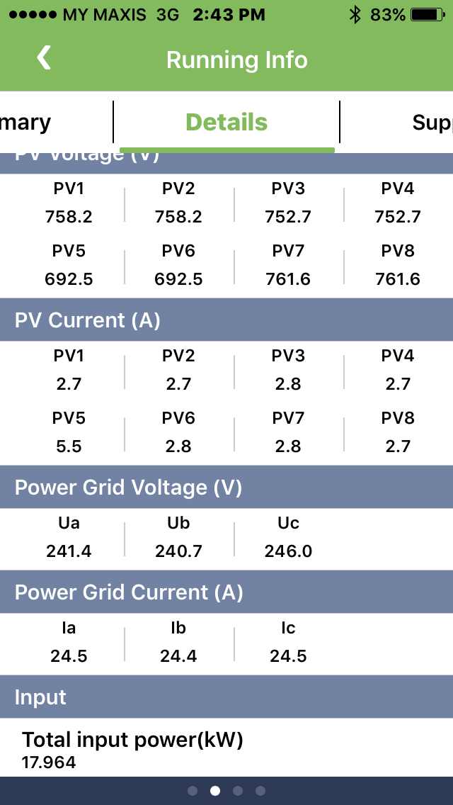
I have done a real time comparison via Solar Inverter.
I clamp the CT on one of the inverter output three phase wire, run the Emonlib current only program and compare the result with inverter real time performance app.
Below is the result:
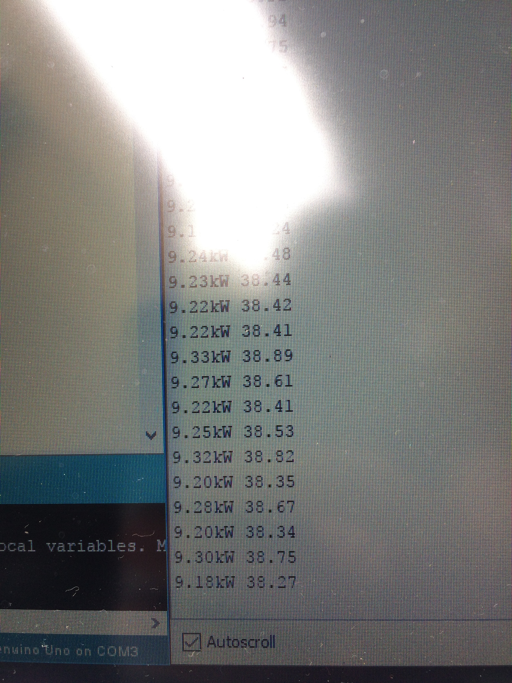
This is the app result on 2.43pm. Line current is 24.5A, but my serial monitor shows around 38.4 A.(ignore the kW). The reading is around 57% high. (Turns out I am only able to attach one image at one time T.T, but the arduino reading is range from 38.27A to 38.82A.)
My first thought is your c.t. is rated far too high for the duty. You are running it at 2.8% of its rated current, and equally 2.8% of the Arduino’s range, so I would expect errors to be building up. I’d expect 5 or 10 % errors, but not as much as 57%.
Apparent power is wrong, your voltage is 240 V. But again, that does not affect the current.
I cannot see anything wrong with your software, so it is time to measure things.
If you break into the c.t. circuit (WARNING: Switch off the inverter first), you should read 8.167 mA, with 24.5 A flowing.
And what a.c. voltage do you read across your 5.6 Ω burden? (NOT the voltage to ground.) It should be 45.7 mV, again with 24.5 A flowing.
The Arduino actually measures the voltage, so it is the voltage that is important. But knowing whether the current is correct should tell us more about where the problem is.
Yes, this is how I am thinking for Arduino Uno, 1024 pin is divided into two. Meaning the maximum accuracy should be (900A/(1024/2)=1.75A per pin increment.
In my case, I use 5.6 ohm Burden Resistor, the accuracy will further decrease.
Because when 900A is measured, the respective voltage at Burden Resistor is 2.376V (1.856A per pin increment).
This is another 5% accuracy loss. (not sure whether the logic is correct.)
Okay I got your point and please allow me to rephrase:
The next step I should do is to clamp the CT onto some stable load, and then direct measure the voltage across Burden Resistor right?
It is not as simple as that, because the maths in emonLib calculates the rms average of many mains cycles. But when it gets below about 2% (rms), errors start to build up in the c.t, in the ADC, and in the maths.
And remember, the Arduino is measuring about 5588 current samples per second, so about 110 samples spread over each full cycle of the wave. As the amplitude gets smaller, more and more samples near the zero crossing point get lost. It is very complicated.
Or stable generation from your inverter. You can do either.
That is correct.
If you can measure the current as well, that would be good (in case your 5.6 Ω resistor is the wrong value).
Okay noted, will take another try once I reach the site.
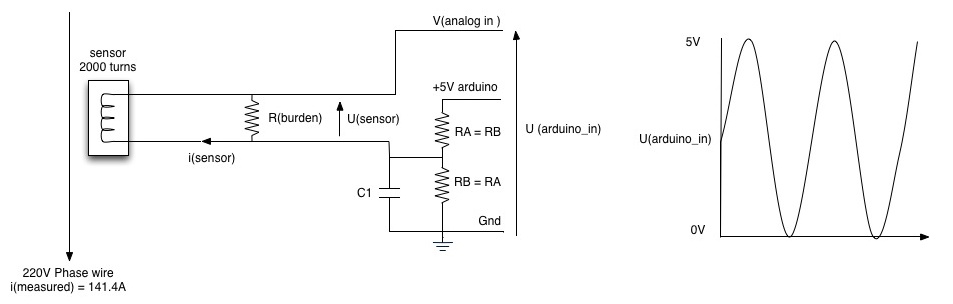
Btw, just to double confirm whether the CT wiring on Arduino got polarity?
As per the picture below, is that important to connect the CT’s red wire to upper or lower side?
It is understandable that when we clamp CT on wire, the CT must face the correct direction else we will get negative result. However, I tried my CT on both direction at one wire, I get the same current result. Is that something wrong with my circuit?
I used multimeter to double check all component’s rating, they are all correct, including the Burden 5.6ohm.
However I found something quite frustrating(or exicting ). While I check the voltage across the divider resistor without clamping the CT to any wire, it shows 2.912V at first divider and 2.105V at 2nd divider.
Thus I unplug the capacitor(10uF) and the result is reasonable as shown in below:
After some google research, I realized there is capacitor with polarized and some isn’t. I take a look to my capacitor and found a minus symbol on it , that means my capacitor is Polarized. (So sorry that I wasn’t from electrical background.)
Do you think this is the main reason that cause the accuracy issue? And why wouldn’t my current capacitor spoil by AC voltage?
Now is 6pm in Malaysia (I am malaysian), I can only buy a new non polarized capacitor tomorrow, provided the shop open on Saturday…
You can only determine the direction of power flow when you know the phase relationship between current and voltage. As you are measuring only current, you can never know that. So, until you add an a.c. adapter and measure real power, the polarity of the c.t, and the direction it points, does not matter. The corollary is, if you measure alternating current with your multimeter, does it read a negative value when you swap the red and black leads?
Another way to look at it: rms means the square root of the mean square. When you square a negative or a positive number, the answer is the same. So ‘rms’ can never be negative.
No. The polarised electrolytic capacitor is fine. You don’t need a non-polarised one. Just make sure the wire marked with the ‘-’ or the black line goes to GND. But if you got it the wrong way round, that would be bad.
You do need the capacitor, it is to allow the alternating current to flow around the loop so that all the voltage from the burden resistor (Usensor) reaches the ADC input.
If all the measurements that I suggested appear to be correct, I think the only answer to the accuracy problem is that the current transformer itself is inaccurate at such a small current.
Bill Thomson sent me a link to a document that says that one particular American standard “defines the required accuracy at 100% and 10% of rated current. It allows double the gain accuracy error and phase angle error at 10% that is allowed at 100%. It has no accuracy requirements below 10% of rated current.”
That means that a current transformer complying with that standard can read anything when the current is below 10% of the rated current, and it still complies with the standard.
This is terrified me hahahahha!
Regarding to the standard issue, I did some research and guess this might be the reason.
Therefore, I am planning to trade in two more CTs for my project: one Arduino with three different rating CTs so that we can have better accuracy to deal with different conditions:
900A, 450A, and maybe 100A.
You are right, I bought the non-polarized capacitor and got them test on my room air-con.
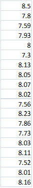
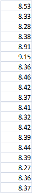
Below is the divider resister voltage with polarized and non-polarized capacitor, as you can see, after I replaced the capacitor into non-polarized type, the divider voltage came equilibrium:
However, I tested both ways on my room aircon, they show quite similar reading. This corroborated your statement .
Below is the testing result:
Aircon spec:
a) Total rated power: 1835W
b) Total Rated Current: 8.10A
c) Max. Current: 10.6A
I set the temperature at 28A, hence I guess both of the reading is not correct and are higher. Besides, Non-Polarized Capacitor’s reading is slightly higher than Polarized Capacitor. It seems like Polarized one has better accuracy, but since the divider voltage is equilibrium with Non-polarized capacitor, I guess I will still stick with the non-polarized one :
Polarized Capacitor:
Non-Polarized Capacitor:
Finally, thank you very much Mr Robert, I think I have got my problem solved already.
The reason I build this project is for the solar project quotation purpose. Before we determine a solar system, client’s power load profile is the most important criteria. Normal commercial energy meter like Fluxo is much too expensive, as I may need to measure the power load at a few sites in one day. It is not realistic to invest so much money for few Fluxo energy meter just to log amps data, especially since I don’t need very accurate data.
This project is so meaningful, thank you Mr Robert and OpenenergyMonitor!
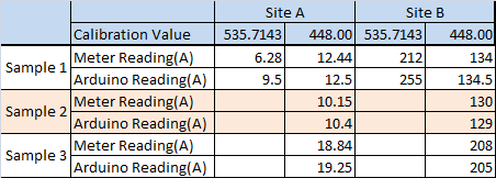
Today I went to two sites for verify my Emonlib energy meter.
The measuring current scale one is around 20A scale and another is 200A.
It is quite amazed that the problem of inaccuracy could be the Calibration Value.
Here is how i get the new calibration value…
I compared the realtime result from energy meter with my Arduino and adjust calibration value manually.
The final value I get is 448. Which the Arduino will give the best accuracy on both 20A and 200A scale.
Here is the comparison before and after change the calibration value. After using the new calibration value 448.00, the accuracy is quite high, ranging from 10 A to 200A.
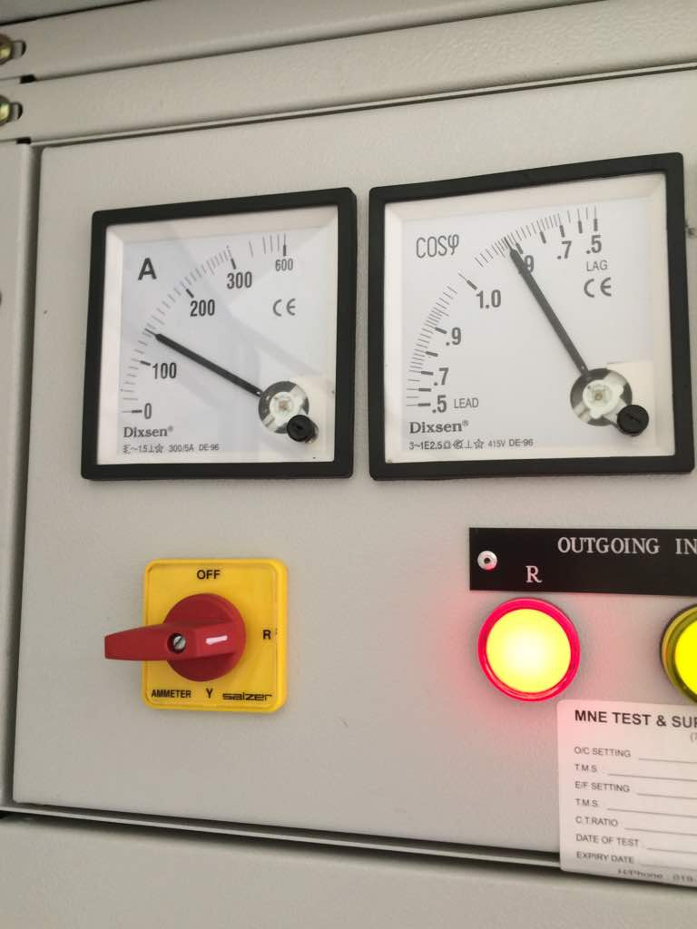
This is some actual site picture show how I acquire the above data:
So, the calibration value of 448 it just a value I created manually. This calibration value somehow show quite acceptable accuracy, therefore I think this is possible to be the correct value.
The next thing I should do is to find a bigger current rating switch board in order to verify the accuracy of this new calibration value at Higher current value say 500A to 800A something.
Any advise from your side?
Thank you very much!
Regards,
Wei
If 448 is the correct calibration constant, then that is what to use.
I would want to check everything that affects calibration, because something, or more likely some things, are not what we think they are. The error - 20% - is probably too big for it to be just one thing that is wrong. There is an article in “Learn” about the errors that can affect calibration, so I would suggest reading that, if you have not done so. The numbers quoted are (mostly) specifically for the emonTx, you might be able to find the appropriate values for your Arduino. You can of course measure very easily the 5 V supply.

 ). While I check the voltage across the divider resistor without clamping the CT to any wire, it shows 2.912V at first divider and 2.105V at 2nd divider.
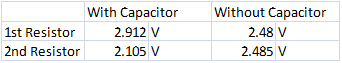
 , that means my capacitor is Polarized. (So sorry that I wasn’t from electrical background.)