Yes, it is correctly wired.
Is it in the positive side of the battery cables?
Look like the 500A shunt is not a good fitting for diybms current shunt, i too have 500A shunt and the measurements is 1/100 of the actual measurement
Ok, a 500A/50mV shunt has a resistance of just 0.0001V per Amp, which is a tiny value to read, however I would expect the INA228 to be able to cater for this, so it could be a software bug.
Floating point math on the ATTINY at such a small resistance value could be a problem.
What is the maximum rating of the inverter/charger you are using? Was 500A a calculated size, or just best guess?
Looking at the INA228 datasheet, it should be capable of reading voltages of 78.125 nV/LSB (0.0000078125V per bit of ADC).
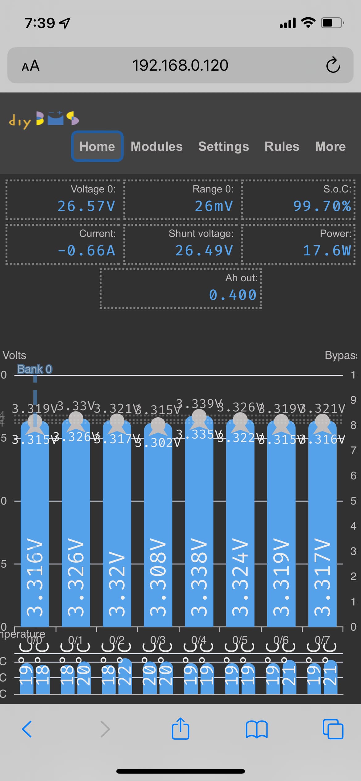
So first question - is the voltage reading correct?
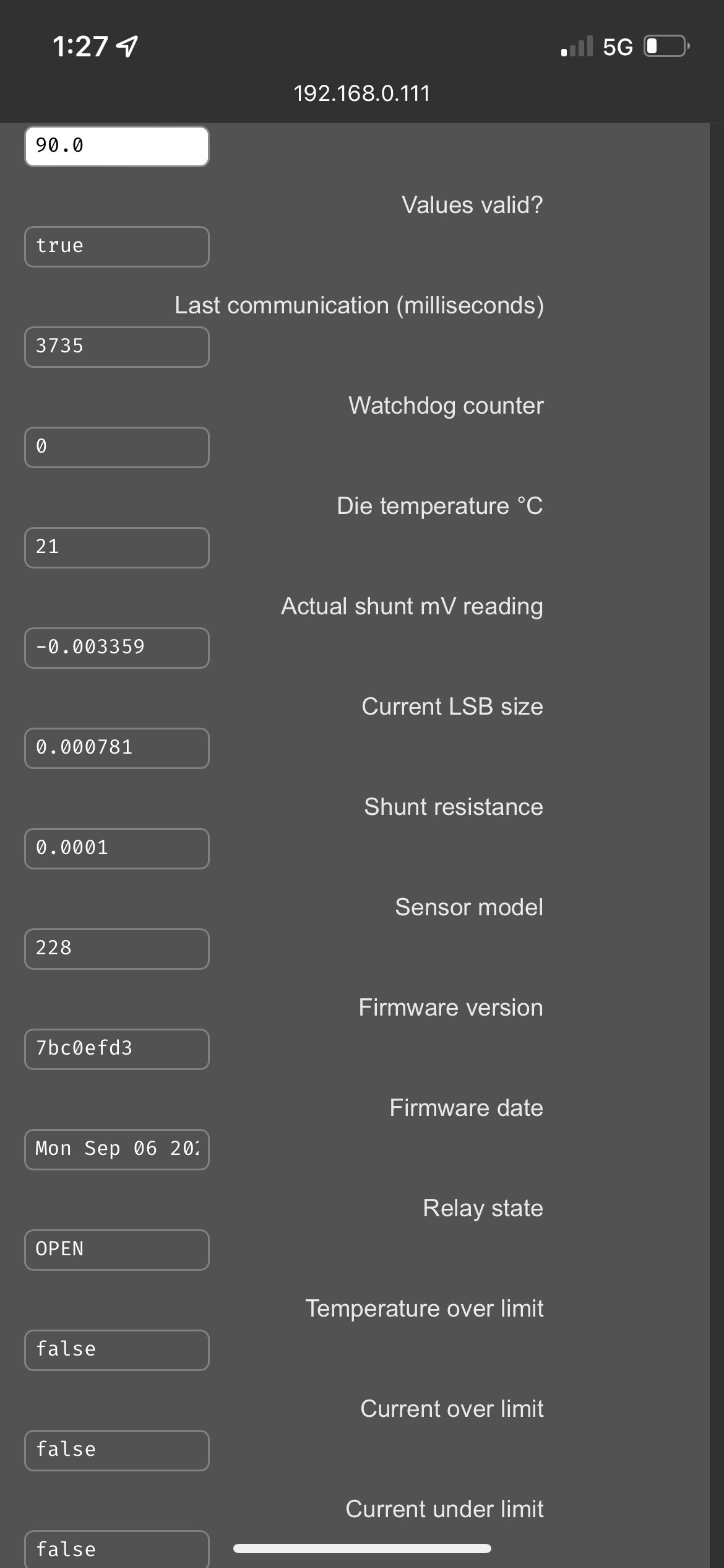
Can you give me the value you see in “Current LSB size” and “Calibration” values from the web interface please?
500A/50mV shunt =   full_scale_current= 500.00A / 50.00 * 40.96 = 409.60 AMPS
                    RSHUNT = (50 / 1000) / 500 = 0.0001
                    CURRENT_LSB = 409.60 / 524288 = 0.00078125
                    R_SHUNT_CAL = 52428800000 * 0.00078125 *  0.0001 = 4096
Current LSB should be 0.00078125
I suspect the “Calibration” value has been incorrectly calculated, it should be 4096.
FWIW here are my values on a 500A shunt that IS working:
Shunt current: 500
Shunt voltage: 50
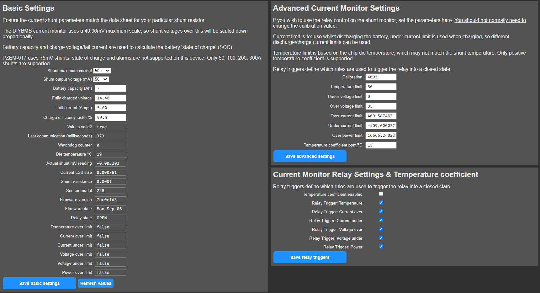
Calibration: 4095
Shunt resistance: 0.0001
Current LSB: 0.0008
Over current limit: 409.5625
Under current limit: -409.6
Over power limit: 16666.2402
Firmware version: 7bc0efd3
I haven’t altered any of the values other than setting shunt maximum current to 500A, battery capacity to 183Ah (soon to be increased), Fully charged voltage to 28.10v and Tail current to 2.5A. Keep in mind these specific settings are specific to my setup and may not be directly applicable to your setup without other parts being adjusted (such as charge controller configuration).
Thanks @atanisoft, that is interesting.
@Xtlife can you confirm the firmware version you have? Is it the same as “7bc0efd3” ?
Here my wiring:
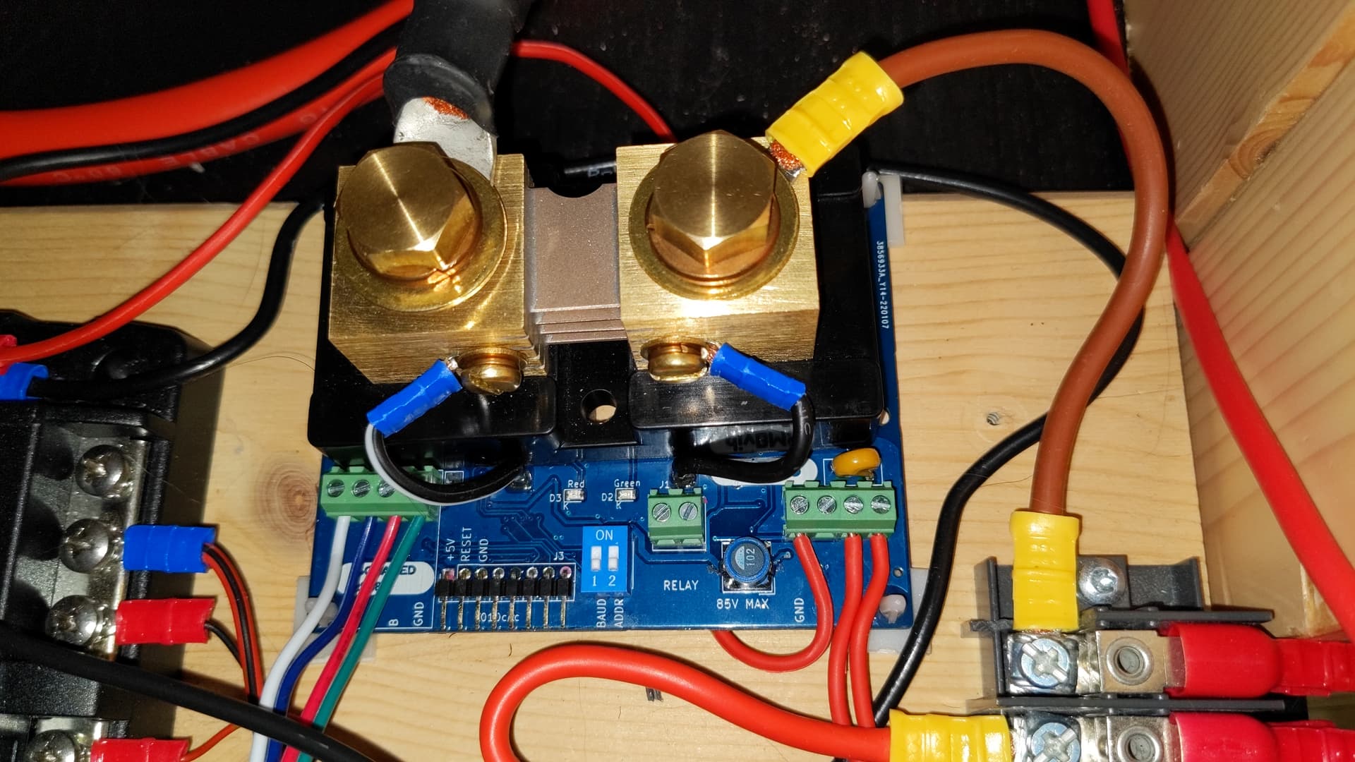
Left = Multiplus + Loads, Right = Batteries
Here the settings:
EDIT: this shows my test-setup, not my real installation!
Ok, I’m away from home for a few days so can’t dig into this until I’m back.
Assume the ground connection to the PCB is using a red cable because you ran out of black!?!
No worries.
No, it was a red twin cable. One marked with a black stripe.
Question, why did you @stuart design the shunt to measure the plus side of the battery instead of the negative?
It can actually measure from either side but only positive side was tested. To use the shunt PCB on the negative side connect the shunt inline on the negative lead from the battery and connect the V++ and VCC screw terminal connections to the positive battery lead.
In theory it should read similar/same as on the positive lead.
The current shunt is working now, lol. Just like Stuart mentions above, its was the 2 voltage sensing wires. Thanks Stuart, you’re the man.
1 Like
Glad its working!
The problem was exactly what you have said, the 2 wire that screw on to the shunt. I checked the screw but i didnt pull on it, i have the ferrels on them and then crimp them to the space connector and that where the problem is they’re were loose and not and really good crimp on my parts. Again thank you Stuart
Umm, not really. Float goes down to 10^-38 or so. That’s plenty. As long as you don’t try to add/subtract numbers that are more than four orders of magnitude apart, you’re fine.
On investigation, I agree, turned out to be a hardware issue in the end.
The code would benefit from using integer/fixed point math though!
I have order 3 sets of PZEM-017 out of china to play with, just a quick question if I run a diode inline to the input for the shunt to the PZEM-017, would this allow me to only measure current in one direction, also if I run a second PZEM-017 and also use a diode in the opposite direction can I program the second shunt in the program of the controller to measure the other direction of current?
I very much doubt it would work, the PZEM is just not designed to measure bi-directional current.