Theoretically its possible, but the code would need to be changed to cater for the 16 bit device. I don’t have any plans to make these changes at the present time.
Yes, that’s what I did… I paid 150€ for 2 chips now ![]()
Cheaper option, but still $21 - pull the INA228 off this board Power Monitor Click
I tried that aswell, but they can only deliver mid-November
Can I use ADM2483BRWZ instead of ADM2483xRW?
There are no differences in the catalog card.
Hi, i am not an expert, but… what about an opamp (high impedance) in the shunt of the pzem017 detecting only the “signal” of the voltage shunt (between -75mv to 75mv).
I mean, we only want to detect negative voltages in the shunt, so after that, esp32 could add “negative” sign to current and power. Of course, we could not use the energy values of the pzem as they will be wrong if we have negative values in current.
I have also read about using an optocoupler for detecting negative voltages, but I can’t find any schematic.
We need another pin in the esp32 to read the opamp output.
Will an opamp disturb the circuit of the measurement of the shunt voltage of the pzem?
@stuart @ross @Bill.Thomson @atanisoft what do you think?
ADDED: For example here I can find a solution:
https://www.ti.com/lit/ds/symlink/opa388.pdf?ts=1662872968696
Point 8.2.1 Bidirectional Current-Sensing
Do you think that with an input current bias of pA it will disturb the pzem circuit?
Hi, anybody? @stuart probably you know much more than me. Do you think if this is possible? Could we “check” the current sign without disturbing the PZEM-017 measurement ?
Thanks.
I’ve not actually taken at look at the internal working of the PZEM017, I purely interfaced with it over the RS485. The way its built doesn’t support current flow polarity detection, not sure if that can be overcome.
I have read that it supports flow in both directions, but, as you say, it always return a positive value
But the value is real. So if we could find any solution “to detect” the polarity/sign of the flow, it will be a great improvement.
But I am not a “circuit expert”. ![]()
Is there anyone here that knows how to do this?
Mikroe have no stock, but I buy same modules from Mouser.eu. Same price - https://eu.mouser.com/ProductDetail/Mikroe/MIKROE-4810?qs=A6eO%252BMLsxmSz%252BFqnPV7jlA%3D%3D&countryCode=BG¤cyCode=BGN
… and work ?
Without the INA chip, will I get any data from the shunt on the controller to confirm that the communication is working and the shunt is correctly written atiny1614?
You won’t get any communication, but the red led should flash several times to indicate a missing INA chip.
Note I’ve made some small code changes recently, so grab the latest files.
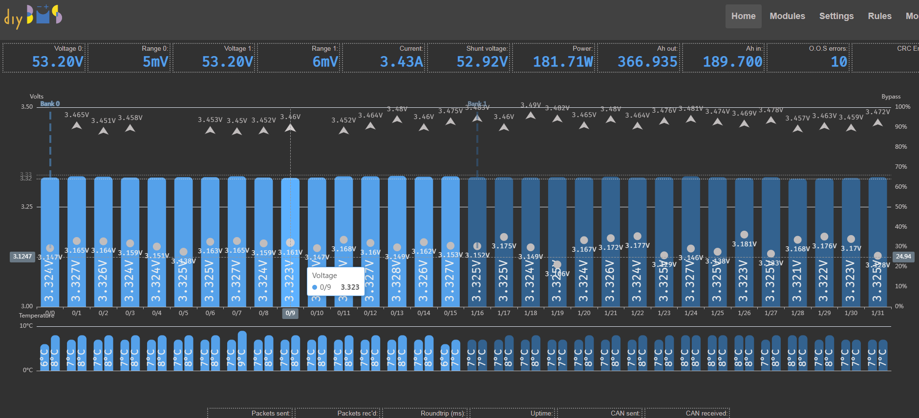
After many weeks of waiting for ina228, I was able to get the shunt working. The measurements look very good, but I have a problem with the SoC being incorrect.
Currently, it is not visible on the screenshot due to reaching the value of 0.00%, which is not true.
The batteries are LIFEPO4 and I would like to keep the voltage in the range of 3.15V - 3.45V for the cells, i.e. at 16s I have 50.4V - 55.2V.
Currently at full charge, the shunt shows a SoC of 46.6%
Can I calibrate to get SoC 0 - 100%?
Firmware version 3f92feb1
Can you try the latest code (only updated yesterday) and report back please?
The code should now “guess” a starting SoC based on the voltage of the cells.
I did a shunt update and it’s a little better.
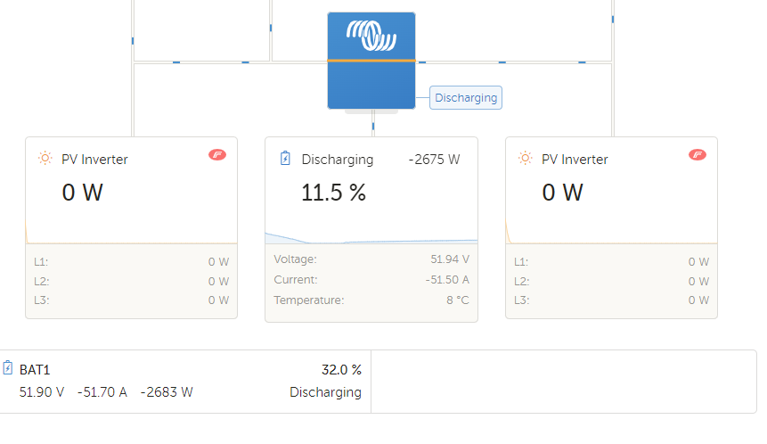
Despite this, Victron provides much more realistic data.
Today I damaged another piece of Attiny1614, I don’t know how it happened, there can be no short circuit. The system can be programmed correctly, but it does not start, the LED does not light up and there is no communication.
Replacing the Attiny1614 solves the problem.
I am worried that I do not know what is the reason, maybe a change of some bit?
Are the values between DIYBMS current monitor and Victron incorrect? They should be very similar.
Have you tried adjusting the calibration value ?

The SoC will need time to calibrate - once the cells are fully charged the current monitor will reset to 100% - just like the Victron does.
No, I haven’t adjusted the calibration value yet.
I assumed that I would wait until it was fully charged first.
And due to the emergency that does not allow charging the PV batteries, I switched the inverter to slow charging from the grid and I am waiting for 100%.
It will take about 10 days.
The thought of constantly killing attina 1614 gave me no peace. When I came to the last trick, I decided to look at the programming procedure in avrdude.
Log made it clear almost immediately that he was not performing a chip erase.
avrdude: Device signature = 0x1e9422 (probably t1614)
avrdude: NOTE: Programmer supports page erase for Xmega devices.
Each page will be erased before programming it, but no chip erase is performed.
To disable page erases, specify the -D option; for a chip-erase, use the -e option.
avrdude: reading input file “diyBMSCurrentMonitor_ATtiny1614.hex”
avrdude: writing flash (14944 bytes):
Only the erasure allowed the doomed chips to run.
So the question is what is written to memory that prevents the program from running?
I do not know how much time it takes to immobilize the shunt, but turning off the power after a few days makes the shunt not start.
That’s a strange one. I don’t think I’ve had that problem with the shunt losing its code.
Perhaps there is some sort of voltage spike on power up killing it?