"CT1 detected" seen on emonpi, emoncms shows vrms however power1 is steadfastly 0

Should I be seeing power data or do I need to enable or configure this calculation? I don’t believe I have missed a step in the setup however I am rereading the guide now.

Is there any way to verify the raw CT data?

CT1 is an SCT013 100A:50ma CT as purchased from the openenergymonitor store.

Edit: I should state that the CT is attached to the single core cable from the meter to the consumer unit. See attached photo.

Thank you.

As the last statement in the Power1 run is >0 try with the CT facing the other way as if it is reading negative the >0 may mean it will not show

John

Thank you John, I have just tried the CT the other way around with the same result, 0. Whilst I am fiddling with the CT I shall try it in the CT2 port.

Edit:
With the CT removed from the power cable and left loose in the meter cabinet both CT1 and CT2 produce random readings, e.g. 174W. When the CT is clamped around either the live or neutral wires and reversed the power value is 0W.

I think I have a supposedly identical SCT013 in a box somewhere from when I was going to roll my own monitoring microcontroller prior to discovering emonpi which I am now keeping back for my PV installation in the future. Is it worth swapping them or do they typically not show this kind of failure mode?

I don’t understand what John means by that. First, did you plug the c.t. in before you powered the emonPi? If not, do a controlled power-down (either via the Admin menu in emonCMS, or the front-panel button and the LCD display, wait as instructed for ½ minute while the RPi closes its files and shuts down), then remove the power. This is because the “emon” front end only detects the c.t. at power-up, it’s not reset/rebooted when you reboot the RPi.

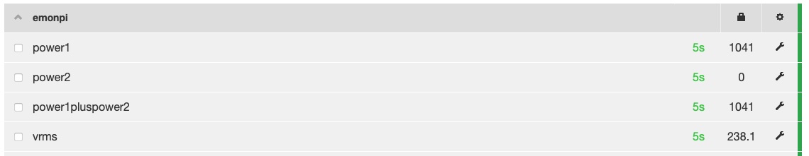
Then power-up again, when emonCMS has started look at the Inputs page via Setup. You should see a value for Power1 (or Power2 if that’s the input you’re using) irrespective of any processing steps.

The other place to look is in the emonhub log (Setup → Emonhub → View log). The emonPi itself is Node 5, so you should see a line a bit like this:

2022-04-04 17:45:47,427 DEBUG    RFM2Pi     1993868 NEW FRAME : OK 5 46 0 41 0 87 0 25 92 0 0 0 0 0 0 0 0 0 0 0 0 124 108 15 0 0 0 0 0 120 86 15 0 205 1 16 0 (-0)

(Let it scroll until you do, then quickly stop it - auto update OFF)

Reading from the left, “5” is the node ID (5 = the emonPi), then the values come in pairs, and they are power1, power2, power1pluspower2, vrms, and then temperatures, etc. The decimal value is (1st + 256 × 2nd), so Power1 = 46 + 256 × 0 = 46W, likewise Power2 is 41 W & their sum is 87 W. The voltage is 25 + 256 × 92 = 23577 hundredths, so 235.77 V.

It’s definitely worth trying the second c.t. It may well be that there are some faulty c.t’s about - there has been a suspicion of that in the last few weeks, so it will pay to try another. Before you do, if you can, measure the resistance from plug tip to sleeve on the c.t’s plug. You should see about 100 Ω if it’s OK.
You can do that with the first one too, but take it off its cable first.

1 Like

Try powering down. Remove power (and AC/AC if used). Unplug CT.

Plug CT back in, then power emonpi.

Wait a bit.

This is the best place to start.

I went for the easy option first - check for the value where it’s easily seen and understood. :wink:

If it’s zero there, then look at and decode the log. We’re old hat at that, Phil might not be.

There’s no need to unplug the c.t, nor to remove the a.c. voltage reference, it does not power the front end in the emonPi.

What’s puzzling me is

Was that with just the one c.t. still plugged in to the CT1 socket? It doesn’t make sense. The c.t. will pick up an alternating magnetic field from anywhere (including an a.c. adapter), and there’s also noise pickup that usually shows up as a few watts, but not 174 W - and on both inputs? You weren’t looking at “power1pluspower2”, were you? Inputs without a plug are grounded, so should read a solid zero, most certainly not 174.

And make sure it’s pushed into the jack completely.

1 Like

Yes I know that is what you say & I also know you do not believe me or it was coincidence, but, I have had it happen that unplugging, and putting back in has solved ‘CT Not Found’ issue for me. No harm in doing so; ensures it is in correctly.

Belt and braces to unplug everything.

Thanks folks, I shall work through some diagnostics today. Update to follow.

The CT I was using shows OL on my multimeter, the spare from my loft shows 101.5 ohms so in the expected ballpark. Is open circuit the typical failure mode?

I cannot explain the 174W, it was mostly 0, occasionally ~10-20W, perhaps it was me just quickly glancing at my desktop screen, I was running backwards and forwards a bit at that time so perhaps not giving it the attention it deserved.

Thank you all for your input in investigating the issue.

The next stage for me is gather typical usage data, we are about to look into PV installation and optionally battery storage but I’d like to get a feel for our typical base load and the frequency and size of our peak loads in order to get the sizing right. I shall take a look at the PV threads next. I want to spec the PV side appropriately, cost v CO2 v savings, battery just feels expensive for time shifting, UPS and avoiding subsidising the energy companies.

No doubt energy paranoia is about to set in, thankfully the below was immediately after I swapped the CT over, the dishwasher has since stopped and I suspect the heated bathroom floor has cut out too since then as I now see ~450W which would be more inline with our “base load” of computer tech, network infrastructure, fish tank pumps and heaters etc.

It’s probably the only failure to reasonably expect! If you feel investigative, you could look further:
It’s fairly easy to get inside the c.t. and look at the connections and check the cable. Open it up completely, and the core, bobbin and a small PCB are retained by a couple of plastic lugs. Spring those aside and pull the bobbin upwards out of the case - it’s extremely easy if you have 4 hands, quite tricky otherwise. You could then check the cable for continuity back to the plug, and you can see the secondary winding - caution, it is very fine wire - and check that also. The SMD soldered on the PCB is a transient voltage suppressor to hold the voltage down if the c.t. is on an energised cable but unplugged. It comes into play at around 9 V, so your meter won’t see it.

I’ve got to admit that on quite a few occasions, simply removing a circuit card and re-seating it
resolved the issue.

The cards were held in place by screws, clips, cam locks, etc, so it wasn’t possible for them to
work themselves loose. The connectors were military grade i.e. made of decent materials.

1 Like