Hi
I’m new to using this and I’ve started by trying the CT sensor with an arduino uno I had .
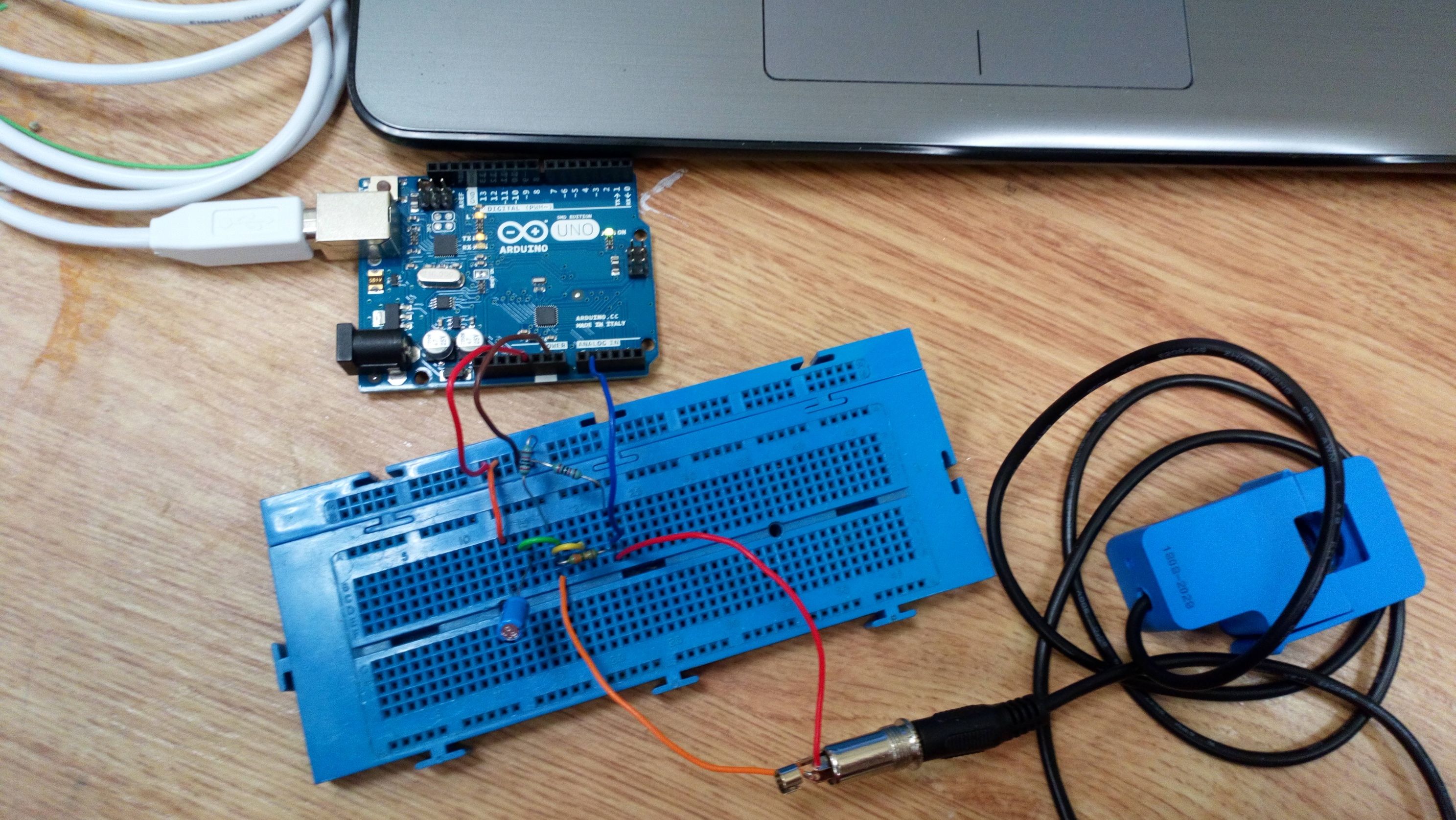
I’ve set up the hardware as shown in the Learn section and I’ve used the code that is given but I’m getting the same output even if the CT sensor isnt plugged in. I’m from Ireland so the code should be relatively the same as for the UK system.
Do I have to change something in the EmonLib.h file or am I just not doing something right?
What are you trying to measure? Experience tells us that a breadboard set-up like that can be susceptible to electrical noise, so if you’re measuring “nothing”, then I’d expect you to see a small and randomly varying current. There are a few points on the FAQ page about this.
Try measuring the current of something like a 2.5 kW fan or convector heater, or a kettle - you should get much more realistic readings.
Remember also that your c.t. is good to 100 A, and it’s not guaranteed accurate below 10 A anyway. My favourite trick to get round that is to have multiple passes through the c.t. That has the effect of multiplying the current, but not the noise, so when you divide down again to get the correct current, the noise has also been divided down.
Thanks for the swift reply, I was trying to measure my laptop charger so I tried a kettle and a fan after reading your message but there’s still no change in the readings.
I have read through the FAQs they were very helpful for a better understanding but still no change so far. I will keep tinkering and see if I can figure it out.
Unless I’m mistaken, your picture isn’t quite the same as the pictorial diagram in the Learn section.
The lead of the resistor that’s connected to the junction of the red/blue wire (on one leg of the CT)
should be connected to the right end of the short yellow wire.
What type of readings should I be getting from this? I seem to only be getting the step changes from the fan, it’ll give a spike when I change each state but will return to noise level after should I not be getting a constant feed of data?
You should be reading the current in amperes. Read again what I wrote in post no.2. And what about Bill’s point in post no.4? It sounds to me as if you’re either picking up radiated interference from the switching, or you’re reading what we call “inrush” current as the motor moves to the new operating conditions. My money is on the first, and you don’t actually have enough current to lift your readings out of the noise.
The obvious question: What current do you expect? What is your “fan” - what power rating is on the label?