I’ve recently purchased a Particle Photon and a CT sensor (SCT013 60A/1V) with a view to monitor the electricity coming into my home. I’ve created a basic prototype of the circuit using a breadboard (which I believe is correct) and have written some very basic code to read in from the connected analogue pin. The value I see from the analogue pin equates to about 1.65V which is correct when no current is present (output on the board is 3.3V and so the two resistors reduce this as expected). The issue is I’m not able to ever get the value to change. I’ve placed the clamp over various power draws (100W light bulb, 4A phone charger) but I can’t get it to move from 1.65V. The CT sensor has continuity between the two wires but it’s like it just isn’t working. From my understanding this model already has a built in burden resistor and should produce up to 1V @ 60A. Am I doing something wrong here? Is there a way to test the CT sensor? Any help would be greatly appreciated.
Thanks for the reply. I do have a multimeter capable of measuring millivolts AC but am unsure if I’m using the correct points when trying to test the sensor. I have one lead connected to the return wire from the sensor and the other connected to the ground on the Photon.
When testing with this setup using the 100W lamp I am seeing some movement when turning it on (25.8 mV) and off (24.0mV).
I also tested it with a much larger load (2000W hairdryer) and the measurements were as expected and much larger (off = 19.0mV, on = 185.0mV).
This leads me to think the sensor is actually working and maybe my issue is more with interpreting the results.
In terms of processing the values I’m simply reading the value of the analogue pin within a loop that has a 1 second delay. The analogue pin returns an integer between 0 to 4095 which is directly proportional to the voltage measured (3.3V / 4096 units or 0.0008V (0.8 mV) per unit).
With no load the value sits around 2048 when I apply a 2000W load the value ranges between 2030 - 2060. I assume this is because it’s AC.
The sure way to prove the c.t. is with the c.t. disconnected from the electronics.
Your meter might not be rejecting the d.c. component in the voltage at the ADC input.
I’m not sure what that actually means, but I think it’s missing something. Take a look at emonLib. In emonlib.cpp and at line 175, there’s the method to calculate the rms current. I suggest you copy the core part of that. You’ll obviously need to change some of the numbers to suit your ADC. The number of samples should cover an exact number of mains cycles - or enough to make any “end effect” error small enough to disregard.
“Root mean square” is the accepted measurement for alternating voltage and current.
I’m in the UK so from my understanding the mains here is approx 230V 50Hz. After reading another one of your posts (Sampling rate of emonLib) I’ve set the value of calcIrms to 112. When initially testing this with the default calibration value of 111.1 the results were way to low when compared to the load being generated, therefore I’ve had to increase this considerably to 900 in order to match the load I’m using for testing. Is this normal or am I doing something wrong here?
What you’re probably doing is not getting close enough to averaging over a complete number of cycles of mains. Even if you know the sampling rate exactly, and nominally have an exact number of samples fitting into one mains cycle, you’ll still have an error as soon as the mains frequency changes as the load on the generators varies. You must expect and tolerate that. If you measure over many cycles, then the longer the averaging time, the less the variation you are likely to encounter.
The fundamental question to determine the number of samples you need is: what is the sampling rate of calcIrms( ) when running on your Proton? You need to know that.
The method is:
Time the period it takes from just before calling calcIrms( ) to just after it returns, using the time-honoured millis( ) function, i.e. unsigned long start = millis( );, and Serial.println(millis( ) - start); after (or it’s equivalent).
Do this for a small number of samples - say 20, for a large number, say 1020, and the difference gives you the time (for 1000 samples) without including the overhead of calling the method and processing the result.
Then choose the nearest number of samples that gives you say 10 cycles (200 ms) of mains. Or longer if you wish.
N.B. I suggest you forget the fallacy of the UK voltage being 230 V. That was an EU standards fudge. As far as I know, the centre voltage is much more likely to be 240 V than 230.
Then, you need to calculate you calibration constant, based on knowing your c.t. ratio and the ADC resolution and reference voltage.
The number of samples looks believable, but it should not affect the calibration while you keep the number close to an integral number of cycles. If you (say) double the number of samples to cover 400 ms (20 cycles - but the mains won’t always be 50 Hz exactly), you should still read the same value.
Backtracking, you now know that you have 208.3 samples per cycle, so when you were sampling 112/208 of a mains cycle - roughly half, the value you got would heavily depend on where your sampling started and ended.
All those numbers are as I thought they should be, but I can’t quite see why your calibration of 800 should be correct! It doesn’t fit with the processing inside emonLib, unless emonLib is finding a wrong number from somewhere, which it is using in the calculations.
If 800 gives you the correct answers and it’s linear, then use it.
I’m an idiot! After re-reading this excellent article Learn | OpenEnergyMonitor I’ve noticed that I have the CT sensor wired incorrectly. I’ve now corrected this and everything seems much better (I’ve had to actually reduce the calibration values down to 60 (hoping this is normal for some setups)).
Thanks for all your help with this, there’s no way I could have got things up and working without you!
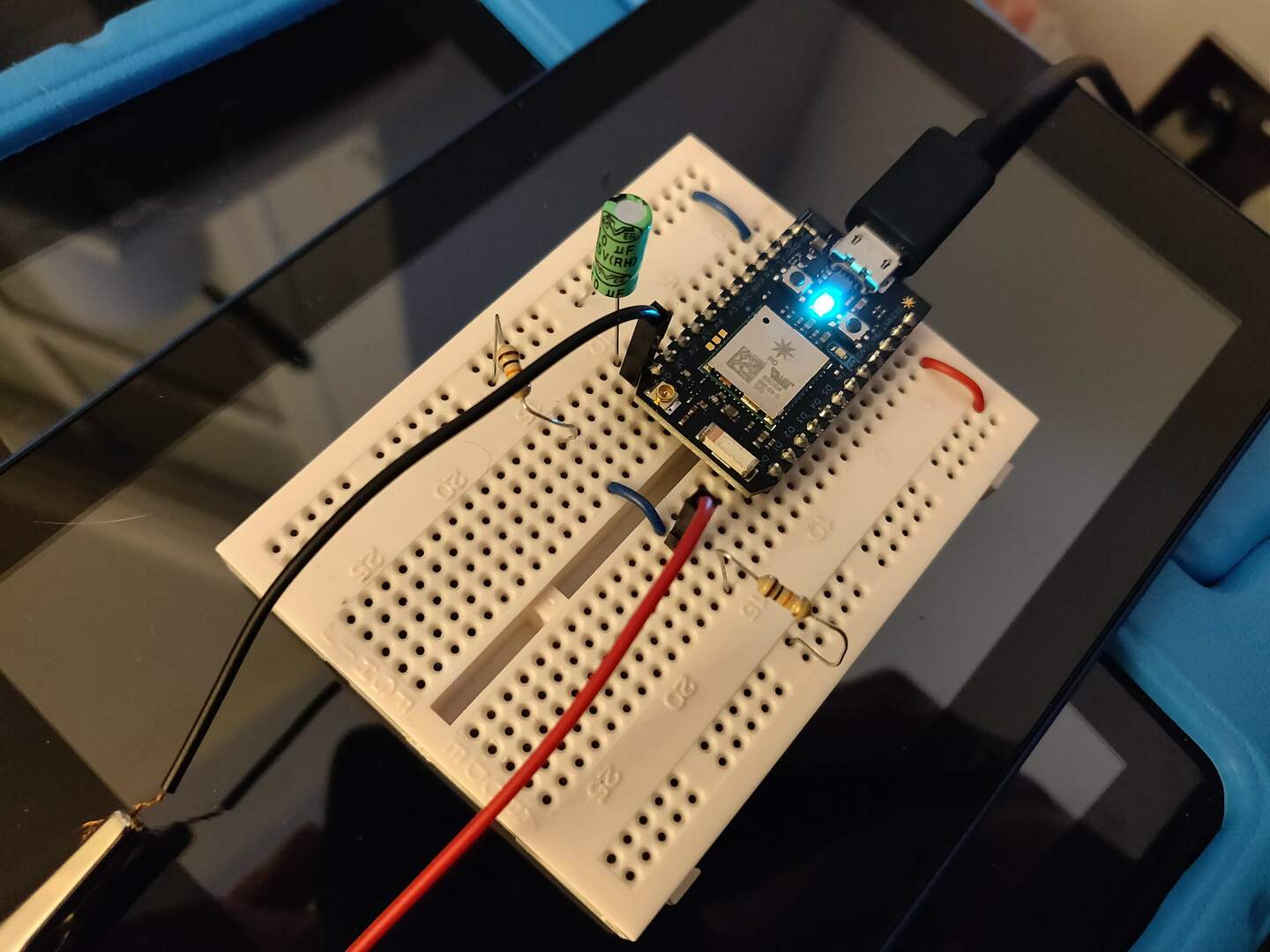
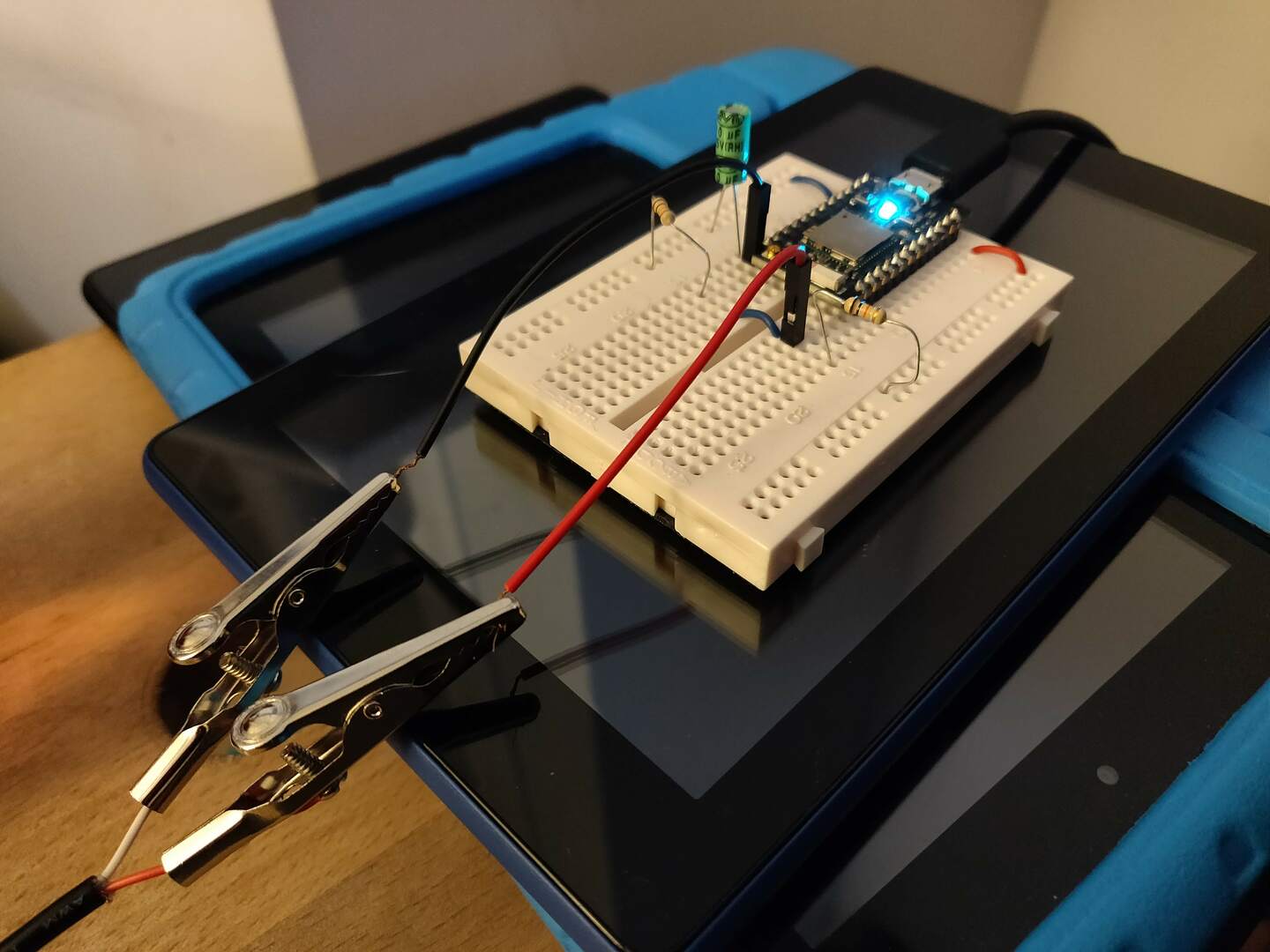
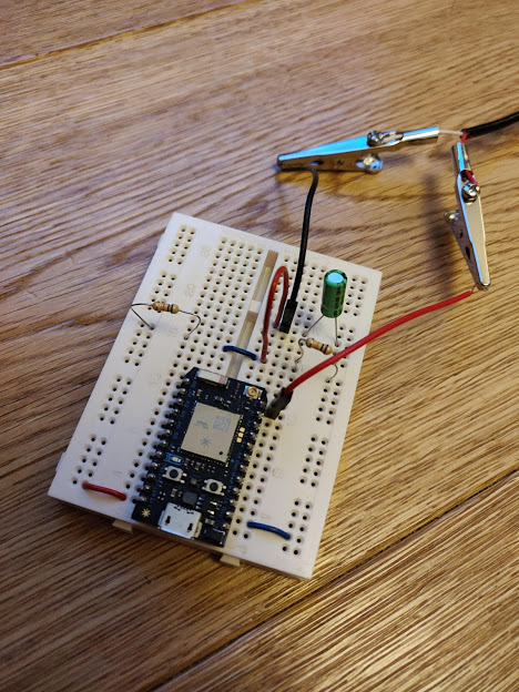
The hook-up of the CT sensor was completely wrong and I was grounding the input pin with a capacitor. The input pin should simply be one of the cables from the CT sensor. The other cable from the CT sensor (the ground) goes via a capacitor but has a 1.65 V feed to it.
I searched the internet for clear images of a real-world working circuit (not circuit diagram) but wasn’t able to find one. Hopefully the picture above will help someone.
That would almost totally kill the output, which explains everything. Being able to transcribe a circuit diagram to the breadboard is an essential skill. Not knowing nor having looked up the pin connections for your board, I’d never have spotted that.