Hey guys.
I’m developing something around my Wemos D1 Mini Pro, a TT-100-SD, blynk, and the Emonlib library.
I reached a point where my arduino could mesure out of one phase (2 phases, one ground, 230v) continously and transmit thoses datas to blynk and make some charts… That was for debugging, getting used to code etc…
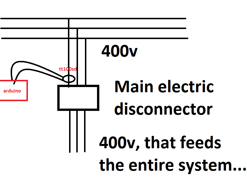
When I clamped my CT sensor to the machine I’d like to monitor (3 feed phases, 400v). All my values are really off, so I changed the calibration but even tho I get the nice value while working (it’s stable but not showing the reals values, ie : when the machine is punching metal I should get a peak of 80 Amps, but it stays really still around 36 amps), when my machine is off and supposed to show 0 amps, I’ve only lost 2-3 amps on my mesures so it gives me something around 33 amps.
I’ve tried many formula, getting the apparent power, multiplying with Square(3)*Voltage * 3 phases … But nothing seems to work.
I did read it was possible on three phases assuming they are correctly balanced (they are) to mesure only one phases with a Amps meter (non-intrusive) and make mesurements.
If anyone knows what my problem is, that would be awesome !
// Premiere partie du code qui définie la base du code. Permet d'inclure les librairies, définir les noms etc..)

#define BLYNK_PRINT Serial // Permet d'écrire ce qu'il se passe sur le monitor
#define BLYNK_DEBUG_ALL Serial

#include "EmonLib.h" // Librairie de mesure de courant
EnergyMonitor emon1; // Creation 'une instance

#include <ESP8266WiFi.h> // Lib Wifi
char ssid[] = "BLINK";
char pass[] = "12345678";

#include <BlynkSimpleEsp8266.h> // Lib Blynk
char auth[] = "xxxxxxxx";//yourauthtoken
BlynkTimer timer; // Fait appel a la librairie Blynk pour lui faire comprendre qu'un timer sera ajouté dans le code

#include <ESP8266mDNS.h>
#include <WiFiUdp.h>
#include <ArduinoOTA.h>


//Début de la fonction sendSensor

void sendSensor()
{
  Blynk.run();
  double Irms = emon1.calcIrms(1480);
Blynk.virtualWrite(V0, ((Irms*400)/(1.732*400)*3)); // Lib Blynk, écrit sur le pin virtuel V0 la valeur emon1.calcIrms(1480)
if (emon1.calcIrms(1480) > 1) {
  Blynk.virtualWrite(V2, 255);
  Blynk.virtualWrite(V1, 0);
}
else if (emon1.calcIrms(1480) < 1) {
  Blynk.virtualWrite(V1, 255);
  Blynk.virtualWrite(V2, 0);
}
}


// Début de la fonction Setup, qui ne se réalise qu'une seule fois (sauf si appel...)

void setup()
{

  Serial.begin(9600); // Ecris sur le monitor en baud 9600
  Blynk.begin(auth, ssid, pass, "192.168.1.113", 8080); // Lib blynk, connexion Token,wifi,mdp, ip serveur blynk, port 8080 ou 81 à modifier
  emon1.current(0, 11.755);             // Courant : Pin input a savoir Analogique0 = 0, calibration (à taton, nécessaire de lire la librairie pour comprendre si calcul possible).
  timer.setInterval(1000L, sendSensor); // timer lancant en boucle tout les "xL" en ms, la fonction sendSensor
     ArduinoOTA.setHostname("EUROPE");
   ArduinoOTA.setPassword((const char *)"123");
    ArduinoOTA.onStart([]() {
    Serial.println("Start");
  });
  ArduinoOTA.onEnd([]() {
    Serial.println("\nEnd");
  });
  ArduinoOTA.onProgress([](unsigned int progress, unsigned int total) {
    Serial.printf("Progress: %u%%\r", (progress / (total / 100)));
  });
  ArduinoOTA.onError([](ota_error_t error) {
    Serial.printf("Error[%u]: ", error);
    if (error == OTA_AUTH_ERROR) Serial.println("Auth Failed");
    else if (error == OTA_BEGIN_ERROR) Serial.println("Begin Failed");
    else if (error == OTA_CONNECT_ERROR) Serial.println("Connect Failed");
    else if (error == OTA_RECEIVE_ERROR) Serial.println("Receive Failed");
    else if (error == OTA_END_ERROR) Serial.println("End Failed");
  });
  ArduinoOTA.begin();
  Serial.println("Ready");
  Serial.print("IP address: ");
  Serial.println(WiFi.localIP());
}

// Début de la fonction loop, qui tourne en boucle
// Il est nécessaire d'avoir une fonction loop la plus épuré possible sous peine de latence, déconnexion, bug .......

void loop()
{
  Blynk.run(); // fait appel a tout les arguments blynk
  timer.run(); // enclenche le timer.setInterval, qui tout les "xL" active la fonction sendSensor
  ArduinoOTA.handle();

}
FYI : If I change Blynk.virtualWrite(V0, ((Irms400)/(1.732400)*3)); // for (V0, IRMS) my mesurements on 230v are perfect and perfectly responding to any amps changes
For real current, I use a Hand clamp, or a fluke logger, both are pretty precise, the fluke is clearly the most usefull as I took some date over hours.
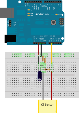
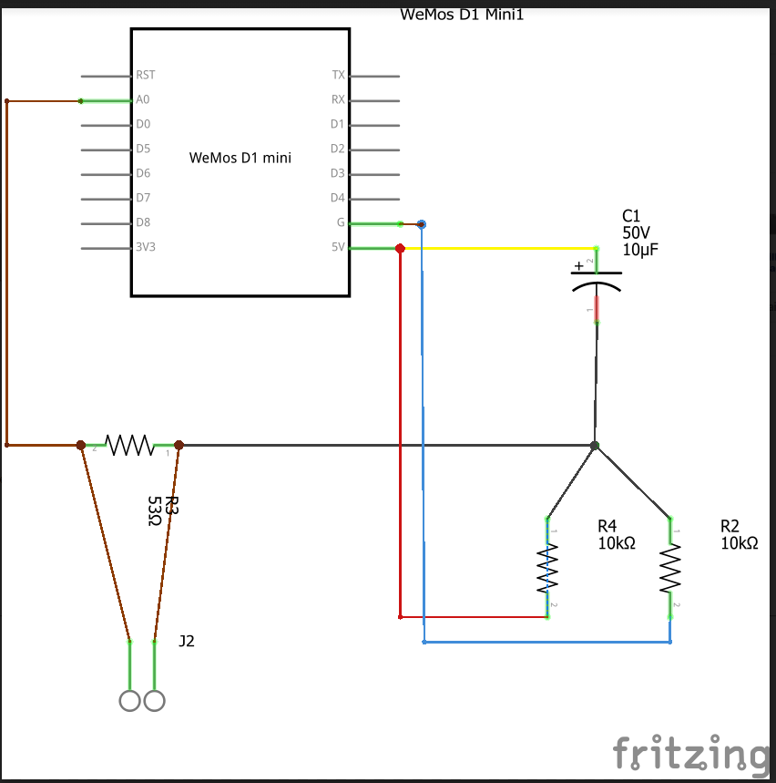
To measure with the arduino I use :
A TT100SD, that has an arrow to know how to plug it (in the flow of the current)
The values are off, it’s not important, what’s important is that there is no spike on the mesurements, nor a lower current while the machine is off.
To be more precise, when I calibrate to have 40A for 40A, when I should get 80A spike I only get 40.6 ~ 41A and when I should get 0 ~ 5 A max I get 39.x A… It doesn’t seem to fluctuate !
Here’s the documentation for the TT100SD https://www.lem.com/sites/default/files/products_datasheets/tt100sd_e.pdf