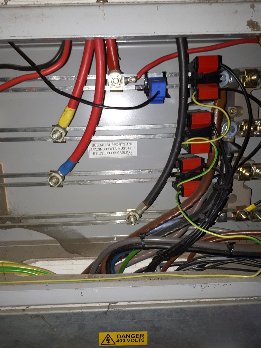
Hi, I have been running an emontx and emonbase since 2017. I monitor the electricity consumption in two circuits max 200amp and pv generation 49kw. It is a 3 phase installation and I have been monitoring only one phase, and assuming that phases are reasonably balanced and multiplying recorded figures by a factor of 3. On one of the circuits I monitor I have placed the CT coil on the bus bar as shown on the attached. The CT coil would not physically fit over the two bars so installed it on one only. My assumption in this instance is that the two conductors are identical dimensions and have the same electrical properties and that any current running through these conductors will be split 50/50. I multiply this current by a factor of 6 to estimate the full 3 phase load. I am now wanting more accurate power measurement in order to control loads (using node-red and MQTT) using excess pv generated electricity. I am intending to install another 2 emontx’s and measure all and sum phases. The long and the short of this long question is will the placing of the single CT coil over the single conductor (of the two) as shown in the picture result in a significant error in the recorded values?
IF (big ‘if’) your initial assumption that the two halves of the busbar are identical, therefore the current shares equally, then multiplying by two will be accurate to within better that the other factors in the system. There will be a very small error due to the adjacent conductor, but as it isn’t right next to the secondary winding, the effect is tiny.
But why not get a split-core c.t. that will go over the whole busbar? If the secondary isn’t 50 mA, it’s not hard to change the burden inside the emonTx to suit. There’s a list of c.t’s that we know about on the “Use in N.America” page in ‘Learn’, though admittedly they are more expensive than the YHDC one, they’re generally better too.
Hi,
is there a reason why you cannot put the CTs on the feed cables as in your picture with the tape round?
John
Hi Robert thanks for your reply, ill look into this larger c.t. - there are already some on there for an old fashioned sub meter.
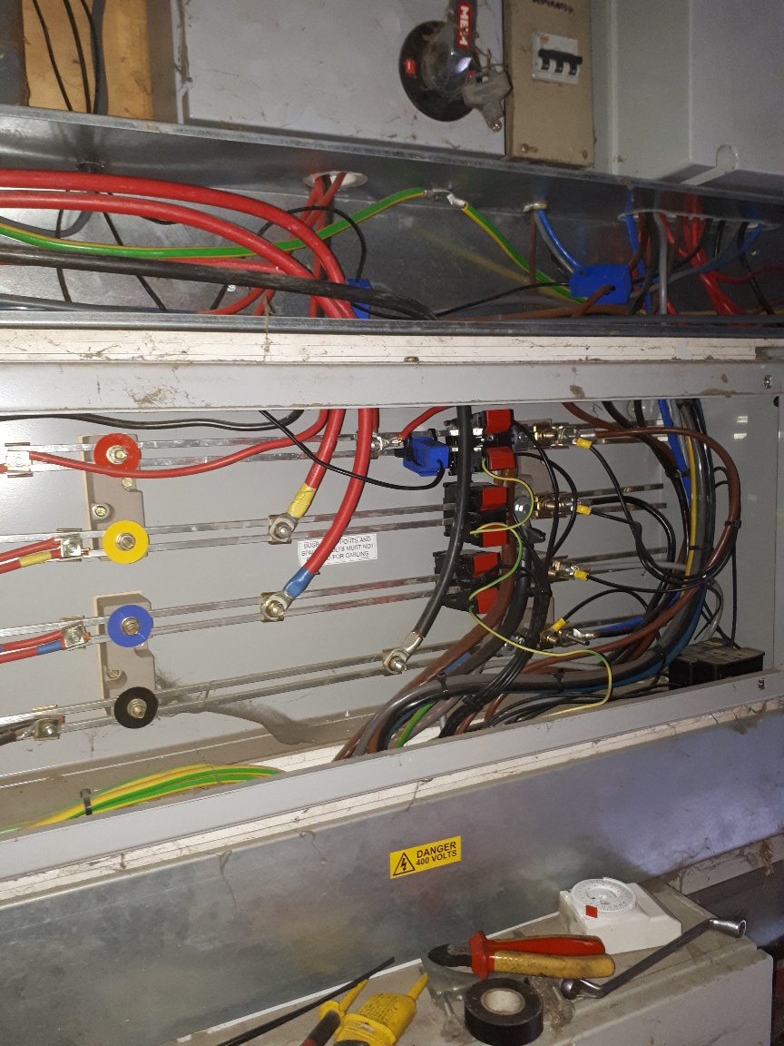
Hi John, you will see from this picture of more of the busbar you will see multiple circuits coming off the bar. I need to measure the load of the combined circuits to the left of my blue ct.
Hi,
are the cables I have marked not the input feeds for each phase to the bars? Red Yellow and Blue. if so if you put a CT on each you should get the total use on each phase.
John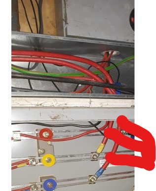
Hi John, if only life were so simple. The installation is on a Farm and has developed over many years, as you can probably tell from the colour schemes and we need to measure two separate parts of the farm. In my picture, the main incommers come from the bottom of the cabinet and are in new colours attaching to the busbar immediatly to the right of the three large black and red CTs. One set of loads is attached to the rhs of these cts and the other set of loads comes to the LHS of busbar. The big CTs run to a conventional submeter for one part of the farm. Its a bit of a birds nest but it works and is safe. As I explained in my initial post I currently measure only line1 and assume load is balanced and multiply by the three phases. Im going to upgrade to a full three phase emontx scheme. I hope this helps. Ill draw a picture if you would like.
Patrick
Those will be worth looking at, but they might not be usable - are they shorted or still connected to something? If they are open-circuit, depending on the secondary current, they could be damaged. They might also be 1 A or 5 A secondaries, which will require a high wattage burden external to the emonTx.
Just to be clear, you need to measure current in the three red cables taped red, yellow & blue, the thin red and all to the left of the busbar supports.
What is the overall width of the bussbar?
Depending on an accurate measurement of the busbar, you best bet appears to be
-
the Sentran 4LSF-XXX-100mA-1.0 series (10 choices of full-load current from 20 A to 300 A) but these will require a second parallel burden resistor adding to the emonTx, or
It would appear that this model has been withdrawn. The replacement, for what you want, appears to be the 1" 4LSG 1.0, with ideally the 100 mA output, although when you completely remove the internal burden resistor in the emonTx, the 1 V output will be quite satisfactory, even though you lose a little resolution. Note this is not meant for use on bare conductors. - the YHDC SCT023R, available in 100 A, 200 A or 400 A versions. These don’t require a change to the emonTx, but the aperture looks to be very tight on the bars, so it needs very careful measurement across a diagonal. The c.t. must be able to fully close and leave some ‘wiggle room’, as any air gap in the core will seriously degrade the performance.
Both will need a 3.5 mm jack plug on the end of the wires - it doesn’t have to be stereo.
Hi Robert, Thanks for that info. At the farm we are rearing chickens and electricity is critical for our operation. We have 200kva supply and 220kva standby generator and lots of switches as per the attached picture. Opening up and looking at the busbar is not an easy task and obviously requires a shutdown. This needs to be scheduled in when we are empty of chickens (they’ve all gone on their “holidays”!) and the tenants in the industrial units are not in. This is usually a Sunday morning once every three months or so! Just thinking about it now, maybe we could cut the actual busbars to leave say a 100mm gap and then link with a short section of insulated cable with crimped ends to rejoin the said gap. Then install the ct’s over this short section. This might be dependent upon the physical mounting of the busbar to ensure it can be held in place.

I wouldn’t try to do that - thinking of what happens to the mechanical forces if you get a serious fault, you’d need a pair of supports each side of the break and fitting them would probably mean a lot of dismantling. By the time you costed in labour and down-time, bigger c.t’s are likely to be not that much dearer.
I got the busbar to 22/23 mm wide by scaling the photo (as I know the size of a SCT-013-000), and if they’re 6.3 mm thick, the diagonal is 23/24mm. That would be just about OK in the YHDC SCT023R (especially if you took ½mm off the corners - and those would definitely be cheaper than the time messing about cutting the bars and drilling for and fitting supports).
(16 mm × 6.3 mm not slotted would be just adequate for your rated generator input, so if the slot is 8 mm, then the width comes to 24 mm - it’s going to be close.)
Hi @Robert.Wall , thanks for your reply. I’ve been trying to source some of these CT’s but not with much success. The ones on Amazon seem to be a bit vague as to whether they are 100 or 200A rated and I’d just rather not get involved with too many technical questions to people who are probably just resellers. I can get them from Spain or Poland, where YHDC have distributors but are you aware of any reputable UK suppliers who I can purchase from?
Thanks patrick
Have you established that the SCT023R will fit on your bars? That’s the important point.
According to the data I have, there are three variants: 100 A rated (good to 150 A), 200 A (300 A) & 400 A (480 A), all with 50 mA secondary windings.
The photograph and the data sheet from here definitely show a 100 A one: https://www.amazon.co.uk/YHDC-SCT023R-100A-50mA-0-5/dp/B07W8GZNS8
This one on Fleabay is obviously a 200 A one: YHDC Sct023r Split Core Current Transformer Input 300a Output 80ma Black for sale online | eBay
even though they claim 300 A.
I don’t know of a UK stockist, I’m afraid, but you could try emailing the Shop (though I suspect they order direct from YHDC in China in quantity).
Hi Robert, No I havn’t been able to ascertain if they fit or not, I’m trusting to your ability to scale the picture and if it all goes tits up ill blame you! …only kidding. I havn’t been able to do a power down to measure and this is unlikely to happen for another two or three weeks, and as Im then not able to do another until 8 weeks later I was going to risk it and hope that If it was a little tight i would be able to bend them in a bit to fit. Those were the two adverts I found and as I want the 200A rated ones they just seemed a little vague as to what rating they were based on a picture and or spurious text! Ill email the shop as you suggested or even try the polish web site.
There’s one in Spain for €10.06 https://www.amazon.es/YHDC-SCT023R-200A-50mA-0-5/dp/B07W6PM4G3
Only one snag: c.t’s are heavy, so expensive on carriage.
If you’re speaking figuratively, then it’s likely there’s no problem.
But… If you meant you were hoping you could actually flex the CTs, thats an issue.
Their cores are made of ferrite which is very brittle. Attempting to bend or flex them would cause
the ferrite to break and render the CT useless.
I’m pretty sure he meant the bars. They’re slotted (look up at the top post). So unless there’s a bolt close by, they should be able to be pinched in a little.
I have now had a power down and opened up the bus bar cabinet to measure them. They were as @Robert.Wall predicted 22mm overall. I have struggled to find the YHDC coils from a source that I feel is reliable so have decided to go with the standard CT coils, mount them on one of the bars and double the output. Following some basic logic and a small amount of internet research it appears that two conductors would each carry half the load. My assumptions being that given that the dimensions are the same on each conductor and an assumption that they are manufactured from the same material, then the electrical characteristics would be identical. N.B. re reading earlier posts @Robert.Wall did say this would be the case back at the start of this discussion.
That was based on what we did with high power d.c. motors. Busbars were out of the question owing to the building layout, so it had to be cable - and I’m talking 630 mm² copper and I think 8 cores in parallel. The cable contractor was instructed to measure each cable to the same length exactly so as to ensure as nearly as possible each had the same resistance and that the current shared equally.