Is there a straightforward way to tell whether the bypass is allowing hot water through? I’m wondering if mine is…
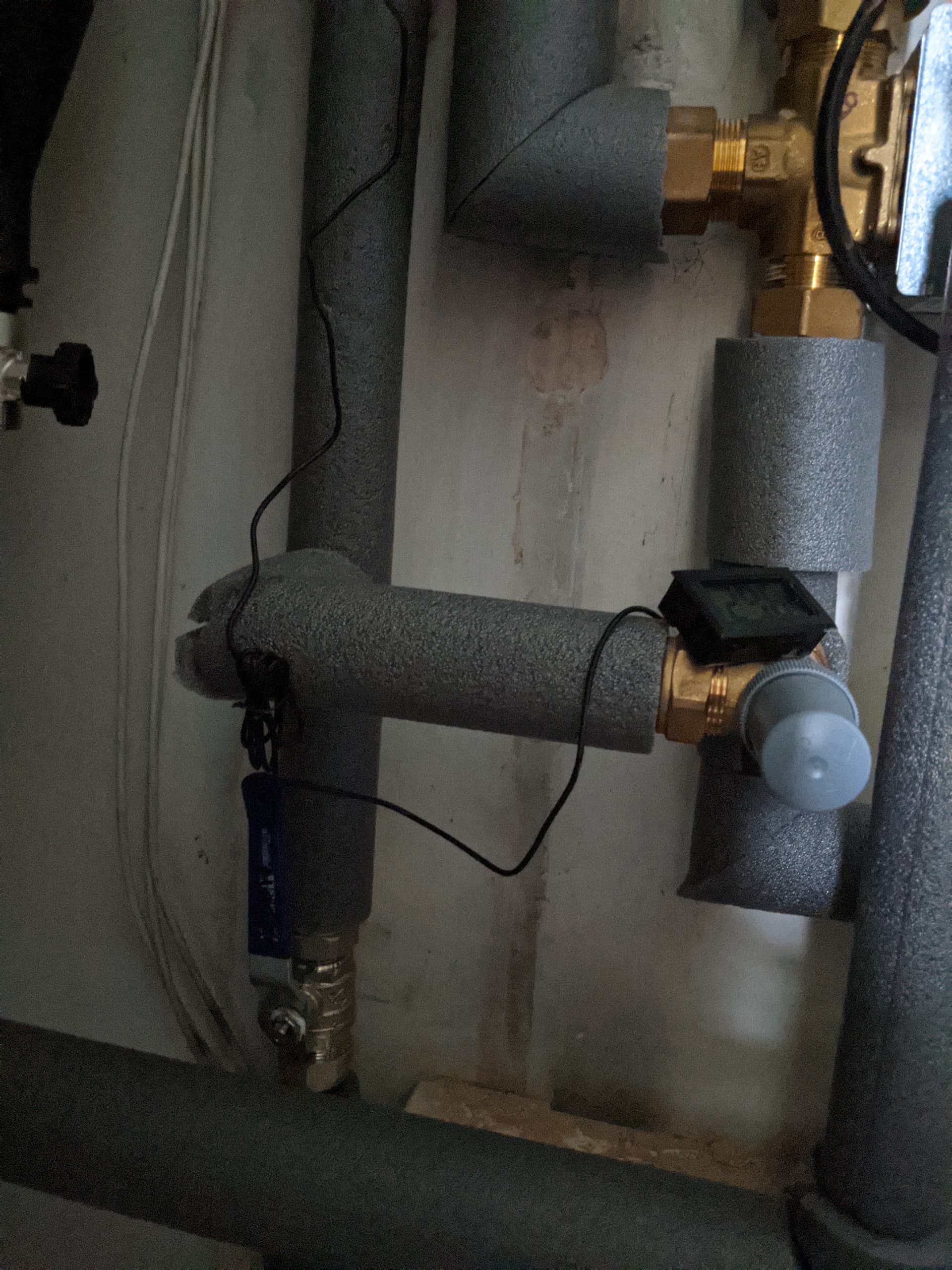
If I measure (with a crude, uncalibrated thermometer) at the return from the radiators just before the bypass circuit joins the return, and before the buffer tank, it consistently reads at least a degree below the temperature reported by the heatpump (which is after quite a long additional bit of pipework). A leaking bypass is the only way I can think that the temperature can rise between the return from the radiators and the inlet of the heat pump, unless the water has already had some heating before the reported Inlet Plate Heat Exchanger thermometer (Daikin 9kW).
Have just done another measurement. Thermometer is slow to respond to changes, but return seems to be about 37.0 before the bypass and 37.6 after it. Seems like too big an effect to just be heat passing through the copper pipe.
top right is the diverter valve on the hot water from the heat pump. The bypass connects to the pipe returning from the radiators, and that then goes to the (buffer tank plumbed as a) volumiser.
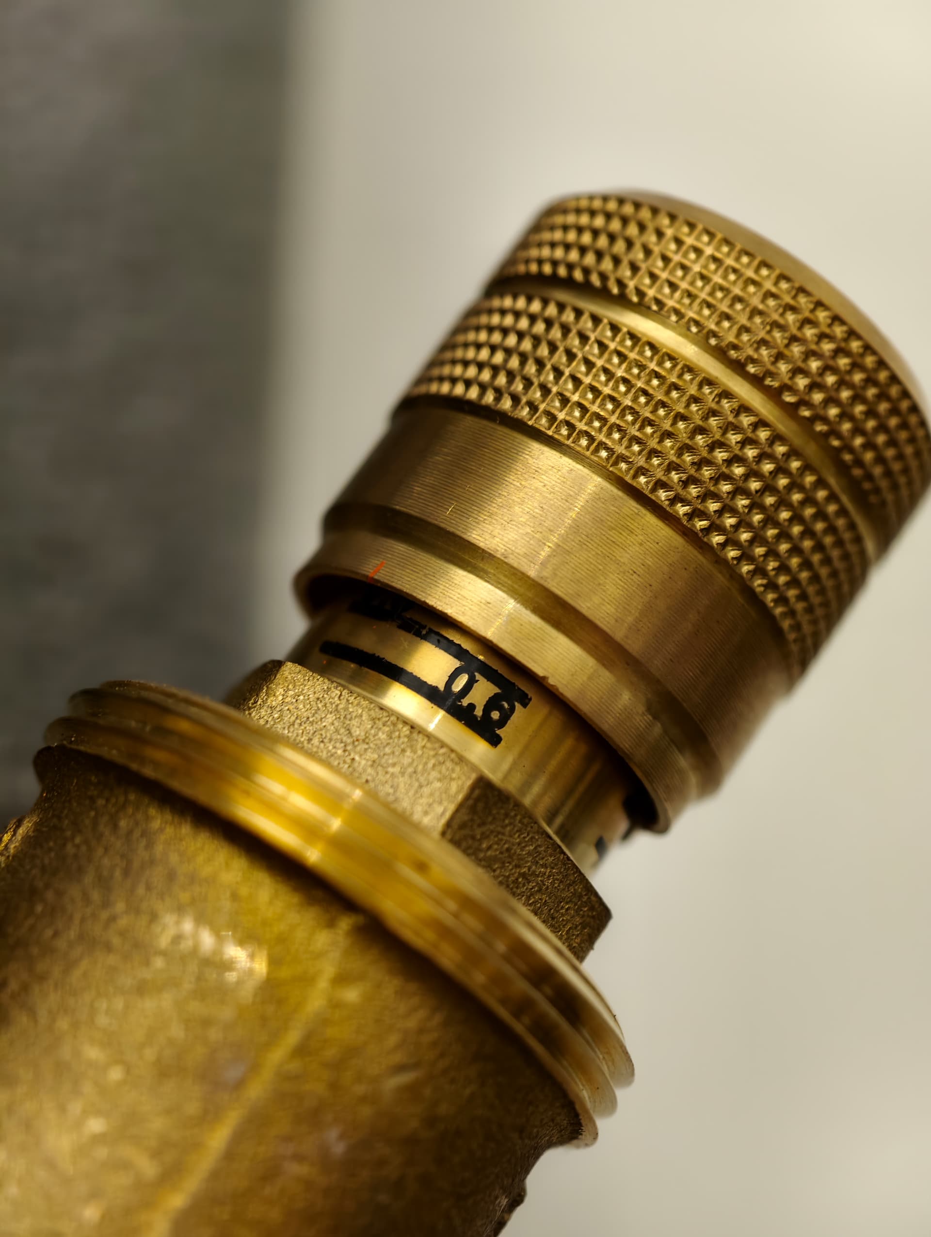
Does the gray cover just screw off ? (It’s quite tight so don’t want to force anything.)
Yes, the gray cover unscrews. I didn’t ever tinker with the control beneath it though so I’ve no idea what to suggest unfortunately. But from what I understand, it relies on pressure to activate and the control sets that pressure point. I would imagine that it will either be bypassing or not and you’ll hear a difference as those states change. This is what mine is set to, in case it helps:
I examined the ABV a little more closely today. Marking it’s original spot, I turned it half a turn each way and I could hear a change in flow going through it. As I closed it further, I could hear the whistle of flow disappear until it was almost gone at about 1/4 open from fully closed. I have no intention of setting any TRVs to anything other than 5.
Interestingly, the flow sensor now reports 28lpm instead of 30 and 16lpm where it was 18lpm. So that looks like approx 2lpm being lost to bypass. If we assume a dT of 5, that works out to 700w of energy recirculating (using this site to calculate energy required to raise temperature). Does that seem right?
I’m glad I looked because I had assumed (I’m learning not to assume with heat pumps and plumbing), that the ABV would be a more binary valve - either open or closed but it seems not!
My assumption was that it was a bit like a TRV - there would be a range of values over which it would gradually open, but that it would be fully open / closed outside of that range. And it should be fully closed when all TRV are open.
At a flow of around 16l/min, I see the return temp rise by say 0.5 degrees across the bypass valve, from say 35 degrees to 35.5. With LWT of 39 degrees, that implies it’s mixing about 2l/min of outgoing water into the return water.
I don’t hear any changes when changing the setting.
During commissioning, the lockshield on the bathroom (first) radiator was fully open, which made it far too warm / unbalanced. I’ve closed it down, but I guess that does mean the ABV sees a less open circuit now. I wonder if that means it’s now passing a little water ?
Hmm… just checking the installation manual, it says that the valve needs to be configured such that the minimum flow is achieved when all possible valves are shut. The problem is that the valve doesn’t have any way of also calibrating the open circuit state, so if the ABV doesn’t fully close when the radiator valves are opened up, then you just have to live with it leaking a bit of water, even if there is now sufficient flow in this state.
Ran through the ‘check the minimum flow rate’ test in the installation manual this morning. Shut down all TRVs leaving just the loop open, fully opened the ABV and ran the test. Got 16lpm. As I closed down the ABV, the flow rate gradually dropped. At 0.5 on the ABV, the pump shut down with a flow error. I don’t recall the flow rate. After a power cycle (MMI reset didn’t seem effective), 0.6 resulted in 5lpm and a flow error. Daikin set it to 0.6.
I’m not sure what the purpose of the ABV is now - maybe it’s to guard against a few radiators being turned off (either intentionally or by thermostatic action), but either way, the ABV seems almost pointless. Did I miss anything?
(It’s fairly straightforward to calculate power. Heat capacity of water is 4200J/kg and 1l is 1kg. So 4200W per (litre/sec) X change in temp. Need to divide l/min by 60 to get l/sec, so it then just becomes
70 * (flow rate in l/min) * (temp change in degrees)
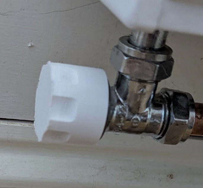
I do have trvs almost throughout - MCs requirement ? Only one non-upgraded radiator is without, but that does still have a turn wheel to close it. But I dont’t plan to use Amy of them. I wonder if there are decorative caps available so I can just remove the heads and put them in a drawer.
I have a small suspicion there may be another bypass hiding in the existing pipework - I can measure the temp. as the radiator flow returns to (what used to be) the airing cupboard, but that’s higher than the output of any single radiator.
I wonder if the installer might have done the flow test with the entire radiator circuit isolated, rather than by closing all the individual radiators - that would have masked the effect of an additional bypass.
I need to get myself a proper thermometer so I can get a bit more confidence in all these various measurements/inferences.
When I bought my Drayton TRV4s for retrofit, they came with a plastic screw on cap that could replace the trv head, I guess intended to turn the valve off for maintenance purposes (changing radiator, etc.). If yours were fitted by the installer the plastic caps are probably in land-fill now, but you might be able to get some off Ebay?
Hmm… just tried a quick test with the heating running normally (all TRV open), MMI reports flow between 15.0 and 15.5.
Adjusting ABV over its full range made not the slightest bit of difference to the reported flow rate. Which is not what I was expecting at all.
Did you encounter much change in resistance in the valve as you adjusted it over its range ?
Update: I dropped the requested LWT so that the compressor turned off and the pump went into sampling mode, with a flow rate up at 18l. Now, when the ABV was almost fully opened, I did hear the change as water started flowing through.
So I can conclude it’s not stuck open or closed, but might still be leaking a bit when it’s supposed to be closed ?
From my experimentation when the heat pump is running normally the heat pump targets a specific flow rate and modulates the water pump to achieve it. So if the heating circuit changes (a TRV opens/closes or you change the ABV) then the heat pump will change the pump power within a few seconds to get the flow rate back to what it was.
There is a Commissioning test in the installer menu on the MMI which allows you to run a flow rate test, you would be better using this for your experiments (see installer manual section 12.4.4). Log in as installer and then goto Commissioning > Actuator Run Test and then select Pump.
This will run the pump at maximum speed, respecting any Pump Limitation (such as 60% pump speed, setting 9-0D) you have setup. It also allows the flow rate to go below minimum flow without giving an error.
Ah that explains why I was only seeing 16lpm - it’s using the sampling limit (which I have set at 6 for 9-0D) when doing the actuator test.
There must be a lower limit on the flow rate for that test because at about 5lpm it would error during the test and I had to power cycle the whole unit.
I stand corrected, I had managed to get mine down to 5.something which is below the minimum of 6 without error which is why I assumed it didn’t error. I have three radiators wide-open without TRVs in the circuit so don’t think I could get my flow below 5.