Hi all.
I’ve been try for a while to connect 9 sensors (DS18B20) to the Emontx bu with sucess.
I’ve 6 connected to a RJ45 to Terminal Block Breakout for DS18B20 and another 3 to other Terminal Block.
If i connect them individually i get 6 readings or 3 readings according to the Terminal connected.
When connecting bith Terminal Blocks in parallel i get readings of “300” in all sensors.
I’ve also updated the node decoder in “emonhub.conf” and i can see all 9 sensors (Temp1 to 9) and have also upload the new hex to the EmonTx and changed the line “const byte MaxOnewire=10”.
Thanks for your support.
Regards,
Rui
I don’t see why that shouldn’t work, I have 7 connected all in parallel but on and esp system not on an emonTx. There was a lot of discussion on the old forum about topologies for connecting multiple DS18B20s. You could do a search on there.
I don’t know the standard EmonTx code but are you making sure in the code that there is enough time for the sensors to settle after sending the readtemps command? And that there is enough time in the loop to read all the sensors now you are reading 9?
Another thought would be to connect the group of 6 to the standard i/o pin for temp sensors on the EmonTX and the other 3 to a second pin. This would need some more adjustments to the code of course. Depending on what you have connected this may be a quick way round the issue.
Simon
How are you powering your emonTx? If you are using the ac adapter, then depending on your actual mains voltage, it might be running out of current.
@RuiFragoso I have spend in the beginning some time to get it working. I’m working with 10 sensors and my TX is connected by AC. And just to be sure, I’ve connected the second breakout via the first breakout to EmonTX.
What are the lengths of your cables to the sensor? I’m using the lengths as mentioned at the bottom of this post. Multiple RJ45 to Terminal Block Breakout | Archived Forum
Is the serial output telling you also 300 for all the sensors?
A long time ago I read the oewire spec. I think it recommended increasing the parasitic resistor if you had a lot of sensors. Might be worth a quick check in the maxim website. In theory the timings etc. should remain consistent apart from the search. You say you can see all 9 sensors, is that in the search code with all 9 connected? It is possible if all 9 attempt to convert at the same time (can’t remember how this code does it, but you can send a ‘all temp sensors’ do convert command) then the power is being drained.
I assume you mean the 4K7 pull-up resistor on the OneWire bus? If you’re running your sensors in parasitic power mode then (at least with the DS18B20) you need to implement an active pull-up. You need the weak 4K7 pull-up at some stages of the transaction, and you need to drive the bus hard high during other stages in order to feed the sensors enough current during the conversion. The datasheet has more details.
In any case, I believe the OEM set-up is 3-wire 1-wire, i.e. +5V, 1-Wire and GND. 5V gets fed to all the sensors on a separate wire so there is no parasitic power in that case.
I think that could well be what’s happening, not because of the 4K7 pull-up (which isn’t involved in the supply in non-parasitic operations) but for the reason Robert pointed out above. The OP hasn’t answered Robert’s question yet, but if his EmonTX is being powered by the half-wave rectifier hanging off the AC-sensing transformer then he may well be putting way too big a load on the 5V rail with 9 simultaneous conversions. Here’s a picture of 6 simultaneous conversions using a 5V Arduino (I don’t have any OEM hardware):
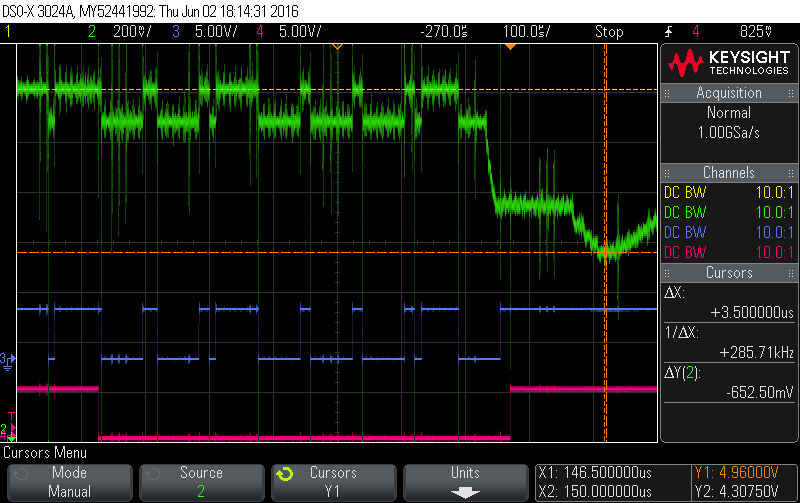
The pink channel is just a trigger channel to indicate when the ConvertT command is being sent. That command is going to all 6 sensors on the bus because of a prior SkipRom command (not shown). The blue channel is the 1-Wire bus and you can see the 0x44 being sent LSB first.
The interesting one is the green channel. It’s the 5V supply feeding the 6 sensors, but after I’ve passed it through a 100R to give me a convenient way of measuring the current. The only thing downstream of the 100R is the 6 sensors. You can see pretty much immediately after all those sensors see the ConvertT command, the 5V supply sags from 4.96V down to 4.3075V. 652.5mV across a 100R represents a current draw of 6.525mA or about 1.1mA per sensor (consistent with the datasheet which says typical 1mA, max 1.5mA).
If that is the source of the problem then a possible fix might be to tweak the code to do one conversion at a time (call requestTemperaturesByAddress() or requestTemperaturesByIndex() instead of requestTemperatures()).
Actually, the more sensors (and cable) you add to the bus, the more capacitance you add. Here’s a picture of one of my 6 sensors trying to transmit a ‘1’ bit by doing nothing in response to the master’s bus pulse:
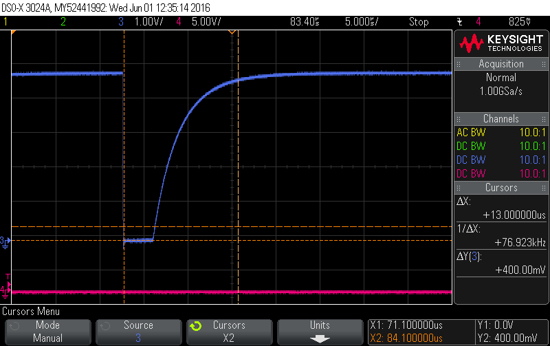
The master drives the bus low for 3.5 usecs, then tri-states it and then checks the bus state 9.5 usecs later to see if it’s high. So that right cursor, 13 usecs after the initial master falling edge represents the time at which the master samples the bus. In this case the 4K7 R had pulled it back high in time, but the more devices you add, the longer it takes, so if that’s the problem here then making the 4K7 stronger might help.
The supply was designed to TWO temperature sensors and an RFM12B radio. The higher current demand of the RFM69CW (and the supply components went unmodified when the RFM69 became standard) means that even with no additional load, the 3.3 V supply collapses somewhere before minimum mains voltage is reached, even with best-case components.
We ask these questions for a reason. If they go unanswered, all anyone can do is speculate.
Hello all.
Sorry for this late reply but I’ve been out of the country for almost 1 week!
Thanks a lot for the quick reply and help from you all.
Here’s some additional details:
- I’m powering the Emontx via AC Adpater (220V).
- Terminal Block Breakout (TBB) 1 with: 6 DS18B20 x 1,5m.
- TBB 2 with: 2 DS18B20 x 15m!!
- TBB 1 connected to TBB2: RJ45 cable with ~10m
- TBB 2 connected to Emontx: RJ45 cable with ~20cm
Both TBB give perfect readings if connected to the Emontx individually (even the one with 15m cables)
Just TBB1:
emontx3 temp1 150s 48.1
emontx3 temp2 150s 48.8
emontx3 temp3 150s 38.8
emontx3 temp4 150s 54.8
emontx3 temp5 150s 37.2
emontx3 temp6 150s 39.3
emontx3 temp7 150s 300
emontx3 temp8 150s 300
emontx3 temp9 150s 300
Just TBB2:
emontx3 temp1 150s 85.1
emontx3 temp2 150s 86.3
emontx3 temp3 150s 300
emontx3 temp4 150s 300
emontx3 temp5 150s 300
emontx3 temp6 150s 300
emontx3 temp7 150s 300
emontx3 temp8 150s 300
emontx3 temp9 150s 300
If i connect all together TBB1=>TBB2=>Emontx i get 300 readings for all sensors.
Thanks once again and sorry for the lare reply 
Rui
I think you are very lucky to have it working with 6 temperature sensors. If it works with all 9 when you connect a 5 V USB adapter to power your emonTx, then clearly you are overloading the internal supply.
If it still does not work, then I think your problem is probably reflections in the (10 or 15 m long) cable.
If you hard-coded the address of each sensor, rather than allowing it to search each time, then you might be able to tell which sensor/breakout/cable was causing the problem.
Thanks @Robert.Wall. I’ll give it a try.
Any quick guidance on how to hard-code the address of each sensor.
Made a quick search on the new blog but without success.
Rui
All the technical information is still available where it always was: Resources > Building Blocks.
There’s a test sketch - connect the sensors one at a time and read the serial number. The older sketches (Github) use an array of addresses - all you are doing is manually coding what your present sketch does when it checks the sensors for the first time.
https://github.com/openenergymonitor/emonTxFirmware/tree/master/emonTxV2/emonTx_temperature_examples
temperature_search
and
emontx_temperature_power
and in this extend the array.
I’ve got that many and they work quite happily in a similar setup for the short run 6.
Hello all.
I haven’t done all recommentdations on this thread, but following a recommendations from @bart. I’ve tried to connect 1 sensor at the time to test the limit of the system. I noticed that, even connecting just 1 sensor on each terminal block i got readings of “300”.
Terminal 1 + Sensor 1 connected + Sensor 2 disconnected = Temp 1 OK (55ºC)
Terminal 1 + Sensor 1 disconnected + Sensor 2 connected = Temp 1 OK (43ºC)
Sensor 1 and 2 have 15m each
Terminal 1 to Emontx connected with an RJ45 with 20cm
Terminal 2 + Sensor 3 connected + Sensor 4 to 8 disconnected = Temp 1 OK (70ºC)
Sensor 3 has 1,5m
Terminal 2 to Emontx connected with an RJ45 with 10m
Terminal 1 + Sensor 1 connected + Terminal 2 + Sensor 3 connected = No readings (all 8 with 300)
Termina 1 connected to terminal 2 with RJ45 cable with ~10m
Terminal 2 connected to Emontx: RJ45 cable with ~20cm
I was afraid that the emontx was not able to recognize all 8 sensors but since i’m also having issues with just 2 sensors it should be OK.
I think theres no “overload” problem but a configuration problem since it works with 6 sensors on 1 terminal block but not with 2 sensors, 1 on each terminal block.
Any thoughts you might wanna share?
Thanks!!
Rui
That’s the App. Note that’s linked from the Building Blocks page “Temperature Sensing using DS18B20 Digital Sensors”
This might be worth reading, from Wayback Machine.
Can you try short cables? Connect the breakouts with short (1-2m) cable to emonTX and to breakout 2. And if this doesn’t work, try also shorter sensor cables.
@RuiFragoso
Can you give us a line diagram showing how you want to connect the sensors, and show the lengths of the cables?
Then another diagram or diagrams showing each combination that works correctly, again showing how you connect them and the lengths of the cables.
Have you loaded the temperature search sketch and do you have the serial number of each sensor?
I suggest you do that, you must naturally connect only one sensor each time. Then add the addresses to the array in this sketch, with all 8 sensors listed.
The sketch is for the old emonTx V2, so you must change the pin numbers, etc, to suit your emonTx, and you must use the same Payload structure as your present sketch uses.
Then add sensors to your wiring one at a time and interrogate the sensors individually, so that you can see when it fails and which sensor when added causes the failure.
Dear @Robert.Wall, i’ve tried @bart’s idea of changing the sensors with the ones with smaller lenght and it worked!
I changed the configuration from:
Terminal 1 + Sensor 1 (15m) connected + Terminal 2 + Sensor 3 (1,5m) connected = No readings (all 8 with 300)
to
Terminal 1 + Sensor 4 (1,5m) connected + Terminal 2 + Sensor 3 (1,5m) connected = 2 readings coming from different terminal blocks and with cables with 1,5m maximum.
Nevertheless, i will have to do some changes in the house which will lead to the need of an additional Emontx. Since this new Emontx will be closer to the sensors from terminal 2, i will have the chance to eliminate that terminal and have 2 Emontx with 1 terminal block each. That will probably solve all the issues.
Thanks you all once again.
Great Community!!!
Cheers,
Rui