It shows an RJ45 and labels the pins 1-8; fine so far. Alongside it lists nine descriptions, with no obvious correspondence to the pins. What does it mean?
It also seems odd that I can’t create a discussion page in which to ask this question? If that is policy, then an explanation of what the policy is would be useful at the point it is encountered.
I agree that diagram is not clear. I always look at the full circuit diagram.
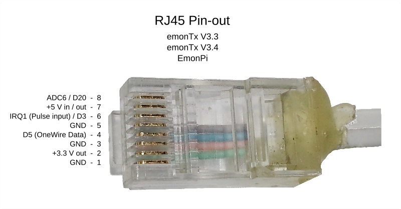
The pins are
1 - GND
2 - +3.3V out
3 - GND
4 - D5 - One wire data
5 - GND
6 - D3 - IRQ1 (Pulse input)
7 - +5V in or out
8 - ADC6 / D20
@glyn.hudson - Can you verify that D3 is capable of 5/12 V in? I don’t believe that, because it goes straight into the ATMega 328, and the max input voltage on that is VCC + 0.6 V. That diagram needs redrawing.