" The ground-fault circuit interrupter , or GFCI, is a fast-acting circuit breaker designed to shut off electric power in the event of a ground-fault within as little as 1/40 of a second."
(North America?) I was installing the emonVs wired directly to the panel. I needed two breakers and happened to have two GFCI breakers. I wired it correctly. When I turned on the second breaker, it tripped. I didn’t try various combinations of which break I turned on first because I’m not a big fan of being around breakers that are tripping (or people, for that matter ) I replaced them with two standard breakers and all appears well.
Does this make senses? Are the E and N tied together on the emonVs?
That’s downright unsafe, if not dangerous. If one breaker trips, and particularly if it’s the L1 one and it’s supplying power to the emonPi, you’ll think it’s safe to go inside the emonVs and it won’t be, the other leg of your supply will still be live. You, in N.America, should have at least a double-pole linked circuit breaker (triple-pole linked for the rest of the world if it’s 3-phase) if you are supplying the emonVs with more than one voltage. And a further linked pole switching the neutral would also be OK (i.e. 2-pole for single phase/one leg, 3-pole for split phase and 4-pole for 3 phase).
Mine are on a 30A “ring main” protected by a 30 mA/30 ms RCD [Residual Current Device], and that has never tripped, and I think I checked at least one emonVs and there’s no connection between neutral and earth, as indeed there should not be - neutral is regarded as a live conductor. If there had been, I suspect a large majority of those supplied to UK users would have tripped and we’d have known about it a long time ago.
You can only blame yourself if you fail to mention critical information.
Now, is your replacement a proper double-pole linked breaker incorporating a GFCI?
How does a GFCI work? Usually, the line and neutral conductors pass through a current transformer. Normally, we don’t do that because we want to measure the current in one wire. When you pass two through belonging to the same circuit, you should read nothing. When you don’t, you see the imbalance and there’s a fault to ground. If you’ve got a split supply, you can quite properly have an imbalance between line and neutral currents because the imbalance is coming from the line current of the second leg of your supply - so you’ll need to put all three conductors (two lines, one neutral) through the c.t of the GFCI for it to work properly.
Your problem is, with two separate GFCIs, you can’t split the neutral current in the proportion of the line currents between the two.
So what you need to do is get a proper 2-pole breaker incorporating the GFCI (we call a breaker incorporating an RCD an RCBO). Something like this.
The reality of the situation is, you almost certainly don’t need a GFCI on L2. There is a built-in non-replaceable fuse, and the only load is through the measuring chain of 6 × 10 kΩ resistors and the ZMPT101B in series. So take the neutral to the emonVs through the L1 GFCI only. At 2 mA of imbalance, the L2 one should never trip. You can get the circuit diagram for the emonVs in the Docs section.
Before you do this, check for continuity between neutral and ground (at a low voltage), just in case a cable got nipped and cut during installation.
I carefully reviewed the emonVs design and I conclude that there is no reason for a GFCI breaker to trip. Next week I’ll be in my panel and will take the opportunity to do this test:
Will an emonVs cause single phase GFCI device to trip?
2-conductor with ground electrical cord
GFCI outlet
switched power strip
emonVs
connect electrical cord to GFCI outlet as one would in wiring it in a box
switch the power strip off
plug the electrical cord into the power strip
plug the power strip into an outlet
ensure: switch the power strip on.
test the GFCI outlet. (If the test fails, get a new outlet and start over)
switch the power switch off
unplug the power strip
connect emonVs to output of GFCI outlet: line (black) to V1, neutral (white) to N, ground (green) to E
plug the electrical cord into the power strip
plug the power strip into an outlet
switch the power strip on.
Did the GFCI outlet trip?
If it did, it is most likely a defective emonVs.
A split phase configuration would be a bit harder to test. In thinking about how I would go about this I would have two GFCI outlets, one on L1 and one on L2. They would have a common neutral; this could the source of what I experienced.
Yes, my bad on not mentioning that my breakers are linked.
My double throw is not GFCI. I forwent GFCI because the circuit is not in an area where there is the possibility of a ground fault.
I had two GFCI breakers that were linked, not a two pole GFCI linked breaker like the one you referenced. My recent post was written when you were posting. I think we’re on the same page.
I agree. If you can’t get a ground fault, what’s the point in trying to protect against it? So why are you concerned?
I don’t see how you can until you have a two-pole breaker with a single GFCI covering both legs and the common neutral.
You need to draw me a diagram showing how you connect the L1 & L2 busbars, the breakers and the GFCIs with their neutral tails, and the emonVs.
No, in my experience; and as far as I’m aware, it’s the same for all UK users.
If you want to demonstrate that, you need to keep any test as simple as possible with as few variables as possible. I don’t see the need for a “power strip” etc, Just plug an ordinary grounded plug with 3-core cable into a protected socket outlet, having put the ends into a screw connector block for safety first. If the GFCI trips, it’s the connector, cable or plug (and yes, I’ve had a brand new junction box fail an insulation test - it took me ages to find the fault because I couldn’t believe it was the J.B.). Then connect the emonVs L1, N & E on the end and check again. Then add your emonPi2. Note the emonVs E screw terminal IS connected to the ground of the 5 V supply to the emonPi2, so a neutral-earth connection via anything connected to the emonPi will give a trip.
Bear in mind that I’m in the UK, where we have either 240 V single phase for most dwellings, small offices and shops and small businesses, and 415 V and higher three phase for everywhere else. 415 V three phase is of course 240 V line – neutral.
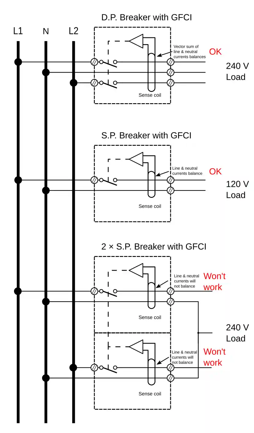
I have sketched out below what I deduce your GFCI is.
The top one is the double-pole breaker and in that, the current sensing coil must surround all three wires. The vector sum of the currents must be zero (else current is leaking - a fault) and so the total magnetic flux from the three currents must also sum to zero. Flux that corresponds with 30 mA of imbalance will trip the breaker.
The second is the single pole breaker, much easier to understand because the currents in line and neutral conductors must be equal and opposite, so again the vector sum of the currents must be zero (else current is leaking - a fault) and so the total magnetic flux from the two currents must also sum to zero.
In the third, I’ve drawn what I think you are describing: two single pole breakers with linked operators, so that either tripping due to a fault will mechanically open the other. In this case, the problem is, what do you do with the neutral? In general terms, the neutral current can be any amplitude up to the higher of the two line currents, and in the direction of either. Splitting the current onto two conductors as I’ve drawn will never work, because you can’t enforce it to split such that the current through the sensing coil matches in amplitude and opposes in direction the current in the corresponding line conductor. Therefore the prospect of NOT getting enough flux to trip either breaker is small - the largest current must be less than 60 mA – and that’s assuming the neutral current splits equally between the two breakers.