Compatible Current Sensors

The YHDC current sensor doesn’t measure up to the desired amperage, and doesn’t fit around the wire in the application I am using it for. The wire has about a 20mm diameter and has a current up to 400 amps. I bought the following current transformer to play around with and see if I would be able to get a reading but so far no luck:

I bought this one because the output of 26.6 mA was comparable to the 0-50 mA that the YHDC sensor outputs. I was curious if anyone else has any experience with hooking up other current sensors and if so which ones have worked.

There’s a list in the page in Learn called “Use in North America”.

That one should “work” - but it’ll only read something like 53.2 A at 400 A actual primary current. How did you connect it? The USA wire colours appear to be fairly standard, so again, that page tells you.

You don’t specify your “desired” maximum current, so I can’t calculate the correct burden value nor calibration constant for you. But if you want to work it out for yourself, you calculate the burden value to give not more than 1.1 V across the burden at your max. current (plus some if you want to allow for new loads you haven’t thought of yet), and the calibration constant is that current which would give you 1 V across the burden.

Eric,

Are you using that particular CT in an industrial/commercial environment, or a residential one.

Thank you for directing me to that page, I did not see that before.

As “Use in North America” stated, I connected the white wire to the plug tip and the black wire to the sleeve. I did this at first with a terminal jack, but also with a self-solder jack. I am still not getting any sort of reading when I test this. Do you think it is worth trying to connect to the jack on the YHDC sensor supplied with the emonPi? If so do you know what color wire corresponds to what probe on the jack?

This is to be used in an industrial environment.

I can’t see what difference that will make. But have you shut down (= powered down) your emonPi after plugging in the c.t? See the FAQ for an explanation - just past half way down:
Q: My emonTx / emonTH / emonPi won’t read the new sensor that I just plugged in. How do I fix it?

OK. I asked because many times a user will think they need a 200 A CT because they have 200 A service.
(In your case that would be 400 A service. e.g. a large house)

As you’ve indicated the CT is in an industrial environment, that’s clearly not the case here.

After rebooting I still wasn’t getting a reading. I have been testing on a small desk lamp, which has worked pretty well when measuring with the YHDC sensors. Is it necessary to test on something with more current?

I certainly think so. A desk lamp at maybe 10 W, something like 0.1 A, and you’re trying to measure it with a 400 A c.t? It’s around 0.02% of full scale. You have absolutely no hope of seeing a current as small as that, let alone of measuring it with any accuracy.

Remember, this c.t is only one eighth of the sensitivity of the YHDC SCT-013-000.

I tested the sensor again on a laser cutter which draws up to 300 amps of current. I was able to feel the transformer working just by the way it vibrated after I attached it, so I don’t think there is an issue with that. I shutdown and rebooted the emonPi after attaching the sensor. Below is an image of the sensor I am trying to use, with the jack attached to the end. I still have had no success.

image

I need to try to establish whether the problem is the c.t., the emonPi, or the method of connection and the way you’re trying to use both.

What do you mean exactly by “no success”?

This seems to say that, using the “shop” YHDC c.t, your emonPi “worked” and measured something. Please confirm that’s the case and it did?

If you substitute a multimeter for the emonPi and use the a.c. current scale, what is your estimated primary current and what do you read on the meter?

Sorry for being unclear. When I have the ct plugged into the emonPi, whether it be the YHDC ct or the 400 amp sensor I am trying to connect, the emonPi gives me a value of about 50. This is even when the ct is not attached to a wire. When the YHDC sensor was attached to the lamp and the lamp was turned on, I saw a spike in the current reading to about 70 or 80 amps. It is for this reason that I think the emonPi is working fine.

I say “no success” because I do not see a spike like I saw when the lamp was connected. When I connect the 400 amp sensor, the value that I read on the display is about 50 amps, the same value I get when the ct isn’t connected to anything at all.

I brought a clamp meter out to the wire I am trying to read and it gave me a value of about 180 amps.

That can’t be true.

(a) The emonPi LCD display does not show current by default, but power.
(b) Current is not sent to emonHub by default, only three powers (Power 1, Power 2 & Power 1 + Power 2) and voltage is sent.

So I’m guessing that your “50 A” is actually 50 W. This is somewhat higher than we might expect, but still reasonable, representing (if you’ve not set the “USA” voltage at 120 V) a current of 200 mA.

Note that, the default assumption is the emonPi is being used in the UK on a single phase, 240 V supply. If it detects an a.c. adapter at power-up, it uses that voltage on the assumption that it’s a UK adapter for 240 V. If it doesn’t, it assumes a constant voltage of 230 V and reports the product of measured current and that assumed voltage as watts, assuming a p.f. of unity.

Yes, OK. But I was asking you what current you measured in the c.t. secondary winding under those conditions?

50 Watts is what I meant, sorry for the confusion.

I ended up having a faulty sensor but I hooked a new one up and it is seemingly working now. What info do I need to be able to calculate the burden value and calibration constant? I am also not exactly sure what you mean by desired current.

OK, the emonPi was designed for use with the YHDC SCT-013-000, to read up to 100 A rms. That c.t. delivers 50 mA at 100 A primary current, and the burden resistor (inside the emonPi) was chosen to generate the correct voltage - about 1.1 V rms - at 50 mA.

The readings are then scaled by using a calibration constant to indicate amperes, that value is then multiplied by the voltage to give the power in watts. All this is done in the “emon” part of the emonPi.

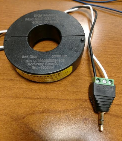
Your c.t. only delivers 26.6 mA, and that’s at 400 A primary current. Ideally, we need to replace the internal burden resistor with a higher-valued one. We could calculate the value either for the full 400 A, or for any lower value you choose - provided the c.t. is capable of that, and for that I’d need more data than the link you supplied gives me. However, replacing the burden resistor is a fairly intricate procedure that I wouldn’t recommend unless you’re familiar with working on printed circuit boards.

I’d suggest to begin with that you set up emonHub to give you the correct power and voltage readings, and accept that you will be losing the ability to measure very low powers. We can revisit this later if necessary.

If you use a web browser in emonCMS, under Setup you’ll see EmonHub, and there, an Edit Config button. That takes you to the configuration file emonHub.conf.

The entry for the emonPi looks like this:

[[5]]
    nodename = emonpi
    [[[rx]]]
        names = power1,power2,power1pluspower2,vrms,t1,t2,t3,t4,t5,t6,pulsecount
        datacodes = h, h, h, h, h, h, h, h, h, h, L
        scales = 1,1,1,0.01,0.1,0.1,0.1,0.1,0.1,0.1,1
        units = W,W,W,V,C,C,C,C,C,C,p

The first three numbers in scales = are scaling multipliers for power1, power2 & power1pluspower2
You need to change each of those 1, to 7.519, [that’s calculated as (400 ÷ 100) × (50 ÷ 26.6) ]
If you discover the calibration is not quite right, it’s OK to adjust those numbers to correct the readings.
Leave everything else as it is.

1 Like

After adjusting the numbers the data seems to be very close. While the machine is on, the current flowing through the wire is about 183 amps, multiplied by the 208 volts is about 38,000 Watts. Emoncms is showing about 40,000 Watts when the machine is on.

Do you have the a.c. adapter? The difference is close to the ratio 220 V : 208 V.

Either way (i.e. you do have the a.c. adapter, or 208 is your ‘typical’ voltage), feel free to adjust that scale factor to give what you believe is the correct value - depending on the accuracy of your instrumentation, of course.

I don’t think I am fully understanding the question. I have the a.c. adapter for the emonPi but I only have it powered using the 5V DC. Would it make a difference if I used the AC adapter as well?

Bill’s just pointed out to me that 208 V is the line-line voltage of a three-phase system in the US. (I didn’t recognise its significance, as it’s not a number I carry in my head.) It would have been really helpful if you’d mentioned that at the beginning, because generally it makes a big difference.

All the OEM shop equipment is designed for the UK single phase system—as I think I intimated earlier.

If you want to measure real power accurately, then you need the a.c. adapter. If you don’t have that, as I told you in post no.13, then the emonPi assumes 230 V, and gives you Apparent Power – Volt-Amperes (VA) rather than real power in Watts. VA is always equal to or greater than power, their ratio is called “power factor”, and it’s always less than or equal to 1. That explains why your emonPi read high, not only is the voltage wrong, but your laser cutter probably has a power factor of a bit less than 1 - and that’s quite normal.

I should say if that machine has a 3-phase supply, which is quite likely given that the line current is 183 A, then the total power is the line current × line-neutral voltage × 3 or line current × line-line voltage × √3 - always assuming balanced voltages and currents. And if everything is balanced, then you can measure real power with your US adapter if you connect it line - neutral, and multiply by 3.

If your machine is single phase connected line-line (as you haven’t actually said it’s 3-phase), then you must still treat it as a single-phase system. You cannot use the US a.c. adapter, but you could use the EU or the UK one, connected line-line using the same two lines as the machine. That would then give you a true measure of real power.

It’s real power that your supplier’s meter reads, and what your firm pays for. (It might also have to pay a penalty charge if the power factor goes too low, but that’s a different story.)

Even when you have the a.c. adapter, you still need the 5 V USB power supply. That’s because the a.c. adapter is only used to measure the voltage, it does not supply power.

You can read more about the engineering basics in ‘Learn’.

This is a three phase system, I apologize for not mentioning that prior. I have connected the ac power supply, and now vrms is giving me a value of about 215 volts.

How would I connect it line - neutral? Correct me if I am wrong, but if the line to line is 208 volts, wouldn’t the line to neutral just be 120 volts?