Yes, the main portal page with the nice coloured graphs appear to give a little higher figures. SolarEdge tech support confirmed for a forum member that the accuracy of the inverter is ±5% as far as energy generation is concerned. Though, that in itself gives no explanation for the difference I mentioned. That should match at least the downloadable data series.
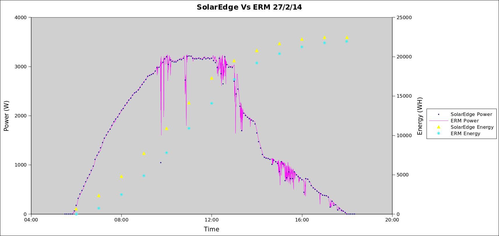
Ah yes, it’s all coming back to me. I dusted off my notes from two years ago and found the attached graph. My precision monitor was reporting less energy per day than their portal so I compared Power and Energy readings for the day. My Power readings (purple line) are true average power over the last 10 seconds (good to about 0.1%) and so are easily integrated to give cumulative energy across the day (light blue asterisk).
Their Power readings (dark blue diamonds) are 5-minute power readings. It’s unclear whether that’s instantaneous power every 5 minutes or some sort of average over the 5 minutes, but their power reading always coincided perfectly with mine (with one notable exception at about 10am). The yellow diamonds are their cumulative energy readings, which gets well ahead of mine for much of the day but tapers off to be only slightly ahead by the end of the day.
It’s hard to fathom how they can measure power so accurately and yet over-report energy. Robert may be on to something.
Hmm, thanks for posting the graph. 0.1% is very high grade measurement, not even some “revenue grade” meters come close. What equipment did you use? I think the 5-minute power values on their site are averages for their respective periods. They wouldn’t match your values so closely otherwise, IMO.
Custom hardware, including an energy IC and high-grade CTs. Normally I’d only quote 0.5% but the power coming out of my inverter has a unity PF, so 0.1% isn’t that hard to achieve. Yes, my revenue meter is only good to 1%.
Can you say a bit more about your rig? You made me curious. OEM provides pretty versatile hardware and software designs with just the needed accuracy (after some basic calibration) but today it’s not exactly hard to build a more accurate system with moderate EE skills. I’m not very experienced in the energy monitoring field, though.
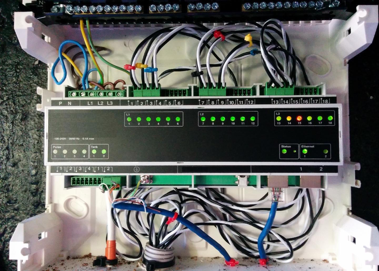
It’s 3-phase, 18 CT-channels (6 per phase), 4 pulse inputs, 2 tank inputs (4-20mA loops), an ethernet interface (2 ports to allow daisy-chaining with other LAN devices via an internal 3-port switch), mains powered, 4kV isolation between the high voltage side and the safe side… all running on an 8MHz AVR but with all the hard work offloaded to dedicated hardware. Here’s a pic with the DIN-rail covers removed…
Thanks for the image and the description. Nice build, and quite a lot of channels you use there Though what I really wanted to know (if you’re allowed to say, that is), is exactly what kind of IC or device you use for your custom monitoring appliance. I’m looking for a possible solution that is easily interfaceable to the Arduino and does all the hard work instead of EmonLib on multiple channels/phases. It looks from your description your choice of parts would fit the bill.
Yes, the two left most screws (P,N) are phase and neutral for the power supply. Internally, they’re completely isolated from the next 4 screws (N, L1, L2, L3) which are used for power measurements. It turns out that’s fairly critical in order to be able to calibrate it. But I guess it also means you can power the device from a different supply to the ones you are measuring (a UPS for example).
In that photo there is only one phase so you can see the brown wire loops from P to L1, L2 and L3 giving you an 18-channel single phase monitor. If you’ve got two phases, you can do a 12-channel / 6-channel split.
That uses the ADE7816, but I’ve looked at a few and they’re all surprisingly similar (or perhaps unsurprisingly?) so don’t be shy about making your own choice based on your own requirements. If you’re not totally competent in all the isolation requirements you can always go the OEM route and stick approved VTs in front of it. And it’ll only ever be as accurate as whatever calibration equipment you can beg, borrow or steal.
Thanks for the advices. I’m currently looking for a chip that doesn’t require a CT, only direct connections from mains (and some passive parts, possibly). There are several of those working in wifi/BT single-socket energy meters. I’m ultimately trying to make something similar, with minimal space requirements. I’m not very satisfied with what these devices have to offer.
I appreciate that you’re aware of the safety implications of not using a CT & PT, but for anyone reading this thread who thinks that making a direct connection to the electricity supply will avoid the inaccuracies introduced by those devices and is therefore a good idea, I have to mention that there are serious safety implications in doing so. Unless there is proper isolation in place and they know exactly what they are doing, they are placing themselves in grave danger.
Oh, yes. You’re absolutely right, sorry. It wasn’t my intention to promote working directly with mains without knowledge and proper safety precautions.
But I don’t remember making a claim that a direct connection in itself would provide better accuracy. After reading what @dBC wrote I’m not even sure any more that even with using a purpose-made metering IC I would be able to make something that provides better accuracy than the EmonTX, calibration included. For the specific purpose of making a single socket meter, components that take smaller space (possibly with direct connection) would be advantageous.
I didn’t intend to imply that you did, but it is a common question that’s asked, because people see the errors that a cheap CT has, and price of a good one, and the size, and think it would be a good idea do away with both that and the voltage one. And generally, it isn’t.
If you’re making a totally enclosed properly insulated and protected unit that reports by radio or visually, and it has no other connection with the outside world, then that’s fine (as long as you’re aware of the dangers when testing and properly isolate your test gear).
Ah, now I see. Yes, my idea is a completely enclosed small box with only the mains fork or double insulated wire with a mains plug and a socket for the appliance/device I’m measuring, and connection to EmonCMS is via RF, using either the EmonTX packet format or my custom one with a custom receiver. I still might be able to use a 30A CT since it’s small, but would also need a transformer and the 2 together might be a little too big for a conveniently sized small plastic box.
Just stumbled across the ADE7816 today and this post while trying to research if there were any products that use it as the spec sheets seems rather compelling. Is the energy monitor you posted a commercial or open product? If so, where can I find more information about it?
I’m afraid neither commercial nor open yet. It is a fully functional prototype that has been designed to meet all the applicable safety standards (although not independently tested/certified yet), supports 1 through 3 phase operation and has been used in a couple of locations for the last few years. There’s potentially a cost reduced version in the pipeline that would probably lose the 4-20mA current loop inputs, and maybe the pulse inputs, but we’re open to suggestions.