I have the schematic for the board but need to know which pins of the 6 are required and which are the relevant pins on both ends as the cable has no DTR and the board does.
So a simple connection diagram for the connection.
All the Arduino stuff is already to go and want to avoid destroying either the adapter or board.
It seems like that information is missing. @Gwil ?
You say your FTDI interface does not have the DTR connection - or do you mean RTS? RTS on the “shop” programmer is used to generate a reset signal, and connects to DTR (pin 6) on the relay board. Also beware that on the schematic, pin 4, labelled “TXD” actually receives data and connects to TXD on the programmer, contrary to convention. Likewise RXD (pin 5) is the line on which the relay board sends data to be received by the programmer.
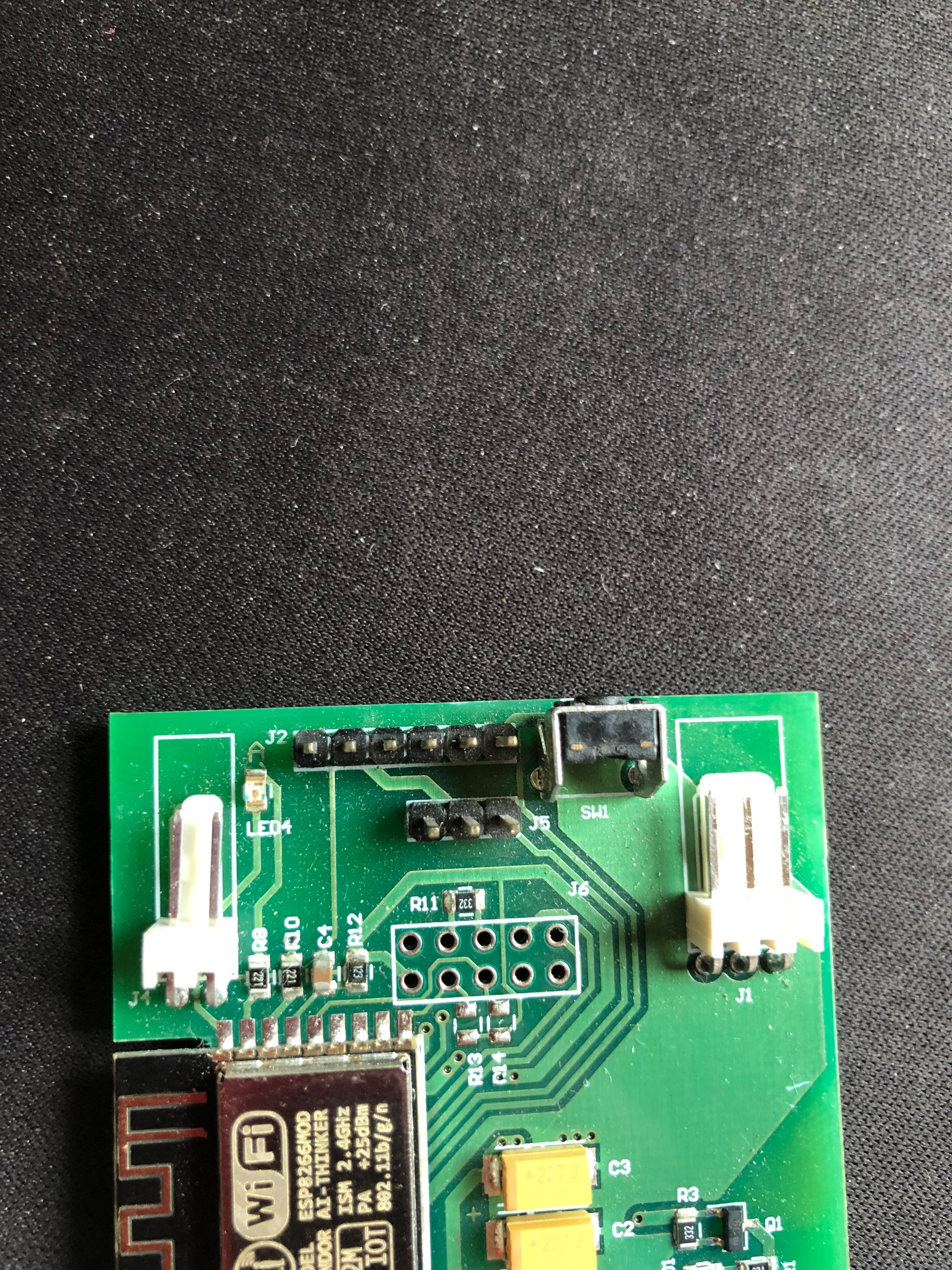
Its already soldered and they all look round so here the picture of the board with no indication of pin 1.
So is the left or right looking at the photo?
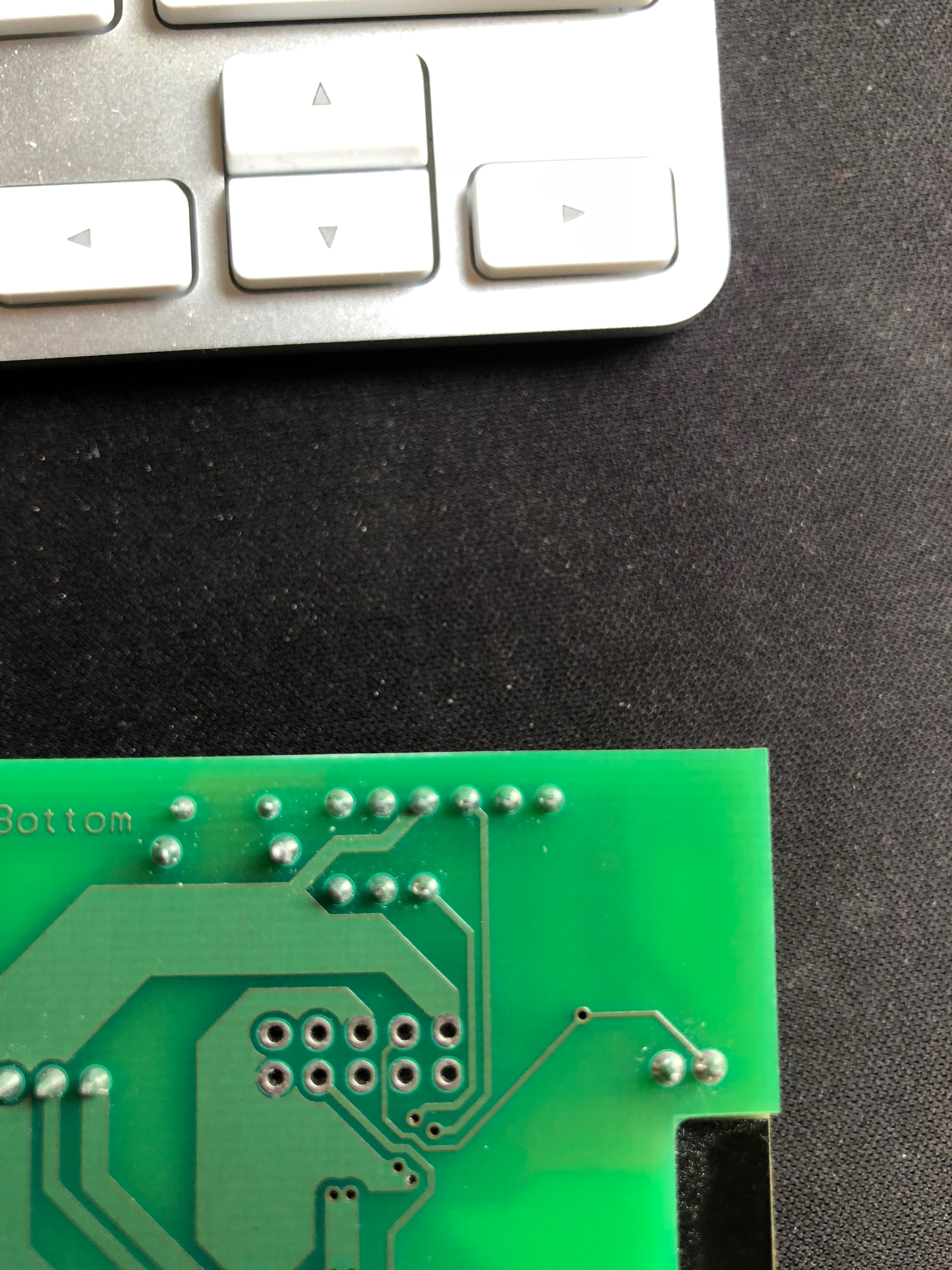
The solderpad on the other side of the PCB.
Can you take another pic so we can see what that looks like?
Sorry 'bout that. I should’ve specified the side of the board opposite of the components.
Normally, the silkscreen outline would have a chamfered corner, or a small triangle
to indicate pin 1. Looks like that’s not the case here. Hopefully, the opposite side of the board is marked.
As a cross-check, if you have a low-voltage resistance range on your multimeter, pin 1 should be common to one side of the LED, R3, R6, R11, the switch and the emitter of Q1.
Thanks to you both and I will check with my meter as a double check before applying power.
Benefits of clear boards marked with pin 1 or a suitable diagram.
Just need to rebuild the firmware as its been sometime since I used the unit.
Used the Linknode 4ch and I have an 8ch unit too, but want to use this one as its already in an enclosure.
Lots of other ESP8266/ESP32 units including a neat M5Stack 2" display module to display info from Emoncms via MQTT and have it control the heating using the inbuilt buttons. Working on adding in Openweathermap updates.
@Meteosat007, could I ask a favour please? what is the make & model of the relay in the 1ch relay board.
Looking at the ‘shop’ photos, I’m assuming it’s a 5V 10A ‘Schrack’ relay, but knowing the relay model would help me. If it is a Schrack, it will most likely be printed on the top, something like ‘RT174005’??