I constructed the circuit for the CT sensor based on the guide here: Learn | OpenEnergyMonitor
I did not use any burden resistor since the 30A/1V version already have a built-in one its 62ohms.
I basically just follow the circuit and copy pasted the given code in the Arduino.
My problem now is that without changing the calibration(111.1) and at no load the current reading started at 5A+.
I’m using a hairdryer as a load and at high it consumes 2.7A+, to achieved this value I calibrated at 19.2. Which is good enough but another problem arise in which when I turn it off the current reading instead of zero is hovering around 1.7A.
First, your calibration - as it says in the ‘Learn’ section, should be 30, not 111.1. I don’t know the voltage that your Nano runs at, it should be measuring the voltage and adjusting the calibration to suit that (either 3.3 V or 5 V), but it might be that this has not happened, which is why you need a calibration constant of 19.2
Second - the ‘zero’ reading. This might be due to a poor, electrically noisy, power supply to your Nano. I believe noise on the power supply can get into the ADC reference voltage, so when the current is zero, it is still measuring the noise on its own power supply - and converting that to a current. You could try a different power supply - preferably one with a linear regulator rather than switched-mode.
Forgot to mention that the Nano is being powered via USB from my computer.
I understand the noise from low current reading but my problem is that at no load the current reading never reach a close to zero value its always greater than 1A unless I lower the calibration further.
If it helps everything is wired on a breadboard and the components I’m using are two 470k resistors, 10uf 16V capacitor. I also cut the jack from the CT using only the two output wires from it.
Unfortunately, that is likely to be part of the problem. We tend to find that people who use breadboard tend to have a noise problem. The voltage you are measuring is 1 V at maximum current - 30 A in your case. Your hairdryer represents 10% of the full scale reading, so you’re measuring about 100 mV.
You could try adding some more smoothing on the 5 V USB to your Nano, and/or you could use multiple turns of wire for the c.t. primary winding - which has the effect of reducing the maximum current you can read (divide 30 A by the number of turns) and equally reducing the calibration constant and the noise.
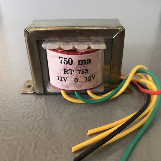
Another question if its ok, I don’t have a 9V adapter/transformer and I’m wondering if a 12-0-12 transformer will work? will a 100k and 6.8k for R2 and R1 enough?
You can add a small capacitor, and it might help; but if you are going to calculate real power using emonLib, it will introduce a phase shift that you will need to compensate for (or add the same phase shift into the voltage measurement).
Obviously, we don’t know the phase error of that transformer, so you will need to adjust the correction for that. The output voltage after dividing down should not exceed 1.1 V at your maximum line voltage (it can be significantly less because your voltage only varies over a very small range - ±10% whereas current goes from 0 - 100%). The calibration constant is the line voltage that would give 1.0 V output from the voltage divider. (“would” because you can design the divider for say 0.8 V rms at maximum permitted line voltage, but you will never actually see that voltage.)
Do not believe the voltage is 12 - 0 - 12 V. It is likely to be much more, because 12 V is at full load, and you have almost no load at all. Don’t be surprised to see 30 V or more across the full secondary winding. Measure it before you design the divider.
One last thing sorry, regarding the multiple turn of wires for the CT, I will divide the calibration constant by the number of turns right? so if I do 4 turns the calibration constant will be 15?