I read carefully the article Installation and Calibration but I don’t understand how to calibration and calculate parameters “234.26, 1.7, 111.1, 20, 1480” in below code:
  emon1.calcVI(20,2000);// Calculate all. No.of half wavelengths (crossings), time-out
  double Irms = emon1.calcIrms(1480);  // Calculate Irms only
I’m really stuck
I’m using arduino 5V, c.t. 100A:50mA, 33Ω burden resistor, 10kΩ divide resistor and transformer 9V
Could you tell me how it work, how to calcutate it?
Thank you so much!!!
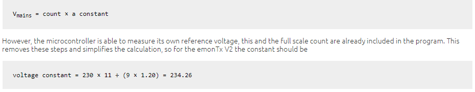
Yes, I know it is difficult to follow, but the last line in each section tells you all you need to know. Written another way:
“234.26” is the mains voltage that gives you 1 V at the ADC input.
“111.1” is the mains current that gives you 1 V at the ADC input.
To calculate those, you must work backwards from the ADC input through the various resistors and transformers to the mains circuit.
“20” as it says in the comment, the number of half wavelengths (zero crossings) of mains over which you sample and average the power.
“1480” the number of current samples over which you sample and average the current. This should be as close to a whole number of mains cycles as possible, the last time I measured the sample rate, it was approximately 5588 current samples per second. (“1480” is no longer the best value.)
“1.7” is the correction for the phase errors in the transformers and the timing error between sampling voltage and current. It’s hard to calculate, it is best to set it on test as explained on the calibration pages in “Learn”.
The calibration constants will be special for your particular set of hardware, so someone else’s values will not necessarily mean you get the correct values.
The values we publish are based on the manufacturer’s data sheets, and should give you the best overall accuracy without individually calibrating your system.
The output from the ACS712 is already biased to 0.5 × VCC, so you do not need the capacitor and the 2 × 470 kΩ resistors. You can use a direct connection to the Arduino input pin.
I have installed an emonpi and an EmonTx so I have altogether 6 inputs from 6 different loads, I want to Calibrate all the inputs using the emonhub scales, my question is once I have a current draw for each of the inputs to convert to KW I multiply the Amp read by the Voltage, is the voltage I use taken from across each of the loads or do I use the reference voltage that the emonpi & EmonTX that is being read as the VMS imput, as they vary by up to 20v AC depending on the load.
Neither. If you want real power (as opposed to VA), what you should use is the power value that the emonPi and the emonTx report, using their own a.c. adapters. If you have not changed the sketches in either, then current is not reported, the default quantity reported is real power. So you shouldn’t need to multiply anything.
Seriously? - then my first thought is you need to have your wiring checked by a competent electrician, because the permissible limit is 2.5%, and 8.33% indicates to me either overloaded wiring or a fault.
Ok thanks, that is what I meant by the reference VMS that the pi and TX report ie what is reported on the inputs!
I have wondered why I get such a fluctuation I will get it checked, I am drawing quite a load at the source as I have averies and have 5 x 2.3KW heaters running plus I have an air source heat pump, so pulling around 70Amps, at full load approx 16KW
First check that both are calibrated to read the same when plugged in at the same place (or the same as a reliable multimeter) because there could be a difference due to component tolerances. But if they continue to show that much difference, you do need to get everything checked.
No, the number that is the calibration constant is the mains voltage that would give you 1 V at the ADC input of the processor. (Therefore, it depends on the resistors around your ZMPT101B as well as things like the actual reference voltage of your ADC.)
The simplest way is to change the calibration constant by the proportion that the voltage you read is in error by, then recheck the voltage your emonTx reports against your multimeter measuring the mains. And adjust again if necessary.
I can’t do the calculation for you, because you don’t say what the emonTx (?) reported. Say your emonTx read 123.4 V when your mains was 127.67 V, and your present calibration constant is 130.
The new constant will be 130 × 127.67 ÷ 123.4 = 134.5 (near enough).
Well, actually the calibration value is currently set up with 154.1. What I’ve done was to adjust the trimpot at ZMPT101B in order the voltage be closest possible of the multimeter value…maybe I’m doing it in the wrong way, right…?
So, as per your explanation, basically all I have to do is:
Connect ZMPT101B to the 127V mains;
Connect the multimeter in the voltage sensor output;
Adjust the trimpot until I got 1V at the voltage sensor output. Read the value in the multimeter (Say 127.67)
Write the value in the step 3 in the calibration code.
Please does the procedure above make sense? Is this 1V peak or RMS?
Electrical engineers always use rms values. Is that not how your mains voltage is specified? I think it will be.
I don’t know what is between the output of the ZMPT101B and the ADC input of your processor. If nothing, that’s correct for the calibration constant. And of course, that calibration constant is affected by the trimpot setting. If there’s anything else between the two, remember I wrote
In theory, it doesn’t matter what the actual voltage that you feed into the ADC is, as long as it always remains within the input range of the ADC. If that is from 0 V to 3.3 V d.c., then your a.c. input must be biased to 1.65 V d.c. and must not exceed 3.3 peak-peak even at the maximum voltage of you mains supply. Remember that in practice, you must reduce that to allow for the 3.3 V not being exactly 3.3 V, the 1.65 V being wrong will likewise limit the voltage swing you can have.
Ideally though, and in practice, you will want to feed it the highest voltage consistent with all those limitations so that you get the best resolution from the ADC. It doesn’t really matter all that much for the voltage input because it doesn’t normally vary from the stated value by more than ±10% - it’s much more important for the current inputs as there, you might want to measure from 100% of maximum down to 2–3% of maximum.
So, my advice would be to use the trimpot to set the rms voltage to about 1.1 V for a 3.3 V ADC, 1.6 V for a 5 V (and if yours is anything else, a ‘safe’ value would be the ADC input voltage range ÷ 3.2 to allow for component tolerances etc), then adjust the calibration constant in the software by trial and error.