I’m not the brightest when it come to formulas etc and electronic, but i am wondering if possible can i run a Allegro ACS758 Series Bi-directional Hall Current Sensor in a emonTx CT port, I know both are analogue output but the CT sensors are based on a max of 1V output but as far as i can tell that the Allegro ACS758 Series Hall Current Sensor is based on a 5V output, as i dont want to fry the emonTx CT port with over votage, can i put a burden resistor across the output of the Hall Current Sensor to reduce the voltage within the specs of want would have been a CT sensor.
Want i am trying to achieve is the monitor a DIY lithium battery back on my hybrid inverter solar battery bank, i know i will have reconfigure the comfig file within the enomTx with some sort of maths calc to read the correct amps
The purpose of a burden resistor is to convert the current output of the c.t. into a voltage that can be sensed by the analogue voltage input of the analogue to digital converter. So a burden resistor won’t help you.
I think (I don’t have time today to read the data sheet carefully) that you must run your sensor from 3.3 V rather than 5 V, and a direct connection, removing the SMT burden resistor, will be needed.
I’ll look into this fully in a couple of days time.
I figured I needed to answer this before it got buried:
Page 2 (Features & benefits) says it’s good for 3.0 to 5.5 V, single supply operation, and the table “COMMON OPERATING CHARACTERISTICS” on page 6 also states that the minimum supply voltage is 3 V and the maximum 5.5 V. Don’t be misled by all the performance characteristics being given for a 5 V supply, this means that to use it with the emonTx you can and you should supply it with 3.3 V - not taken from the emonTx unless the emonTx itself is supplied by 5 V via the USB or FTDI port (the internal supply from the a.c. adapter cannot provide sufficient current) and check the Wiki if you’re using any other add-ons to your emonTx - like temperature sensors, because there’s a limit to the current you can take from the 3.3 V terminals.
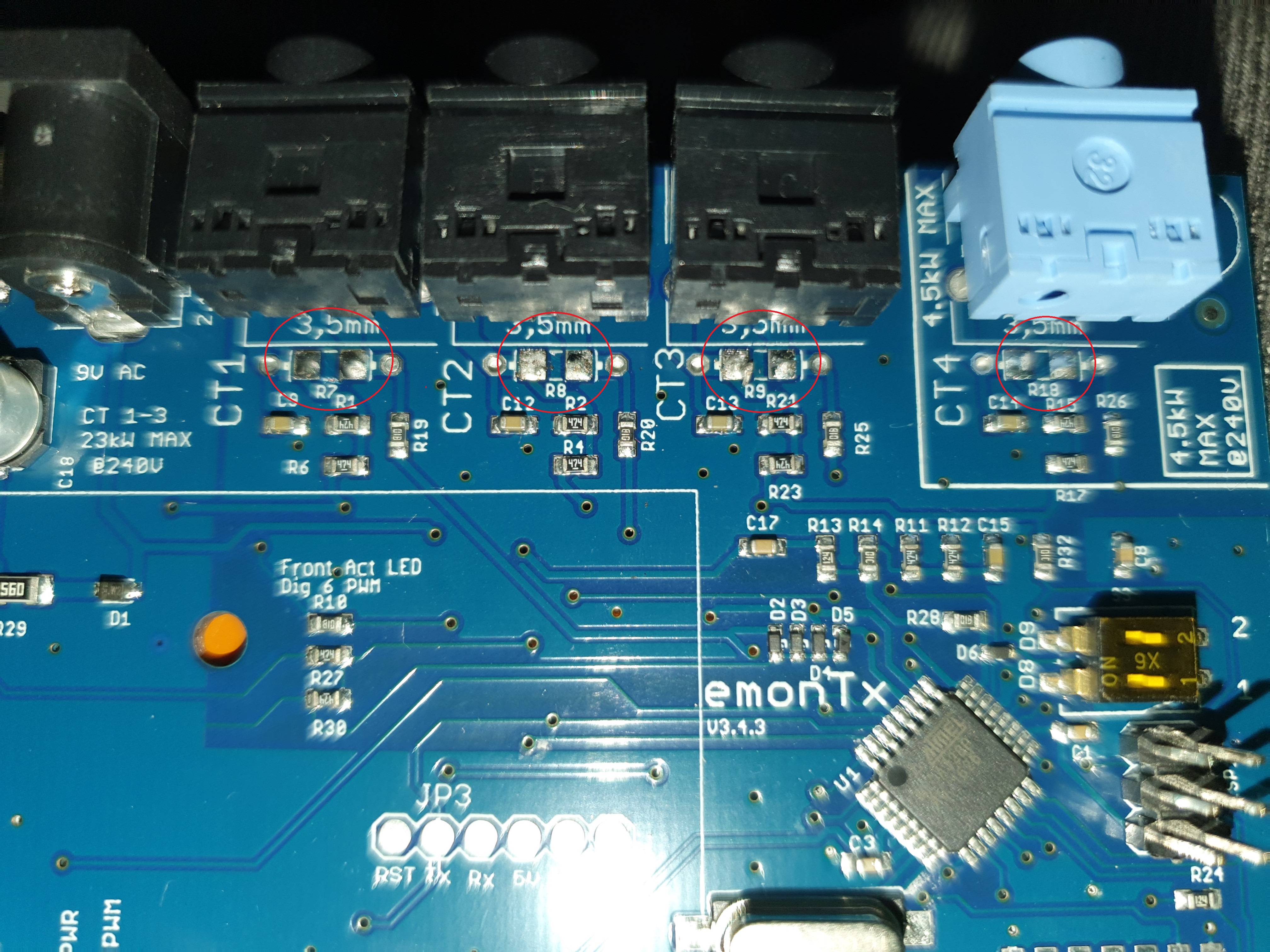
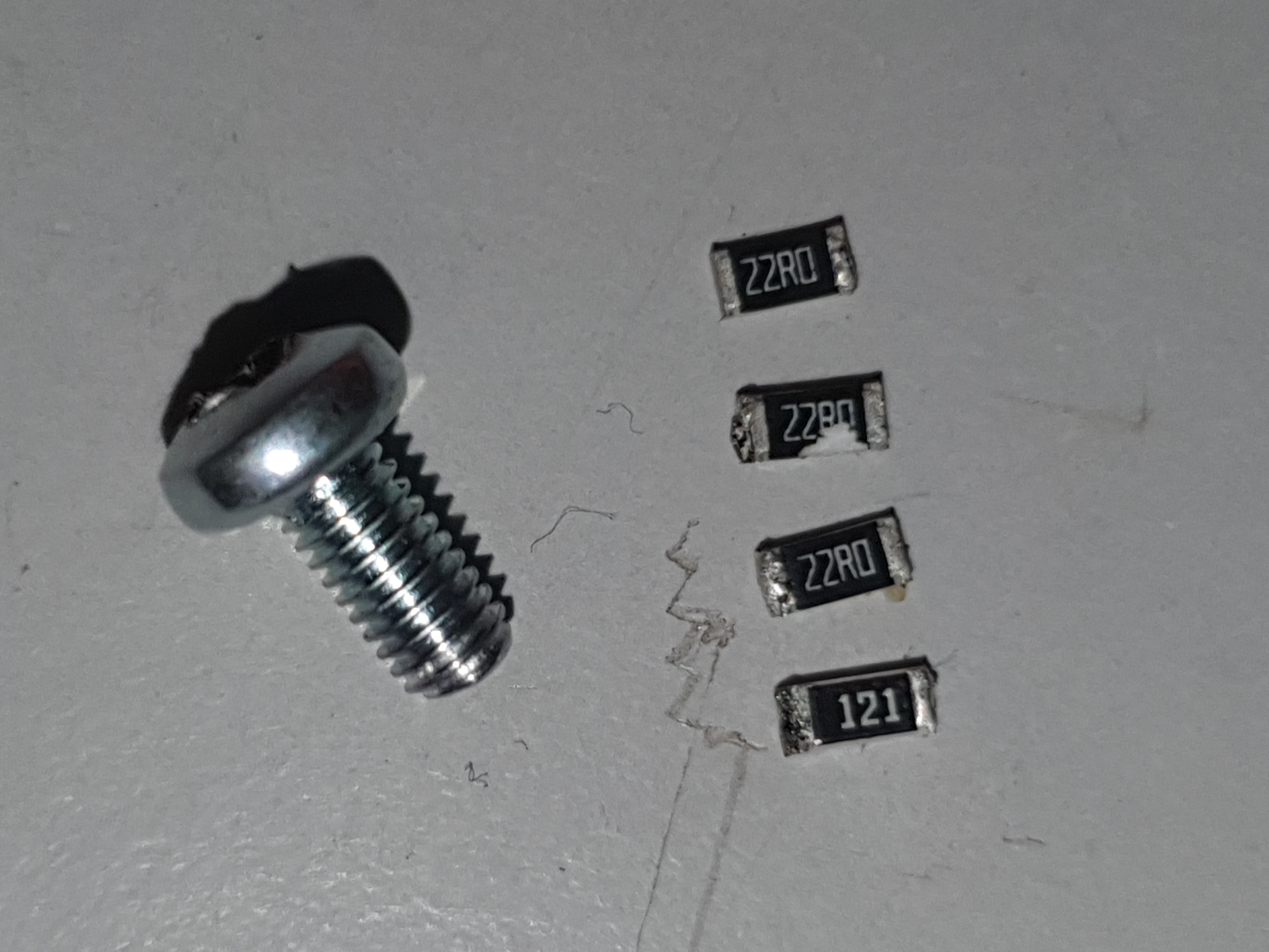
As I mentioned, you need to remove the burden resistor for the input you’re using. It is the larger SMT resistor immediately behind the jack socket. You can use the hole in the pcb that’s furthest from the a.c. adapter (voltage input) socket or the plug sleeve to connect to your ACS758 output pin.
The table also states that the quiescent output voltage is VCC/2. The emonTx’s analog input will give you a value of 511 using analogRead(inPin) with zero current flowing. (Or it should do - expect the value to be a few counts either way. In your sketch, you first need to subtract that - we call it an ‘offset’ - and be prepared to adjust that offset accordingly so the the result is zero with no current flowing.
And on the next page - Performance Characteristics - you have the sensitivity specified, which should allow you to calculate what to multiply the number you have by to give the current in Amperes:
The ACS758 will give you 0 V to 3.3 V out for maximum negative current to maximum positive current, and these voltages (and hence the currents) correspond to the numbers 0 - 1023 when you use analogRead(inPin), with zero current giving you 1.65 V or the number 511. And from that, you can calculate a “scale factor” which you apply to give the current in Amperes.
I can’t help any more with that because you haven’t said which version you’re using.
Now your sketch (“the comfig file within the enomTx”) won’t use emonLib for this input, so where the standard sketch does calcVI( ), you’ll need a line that will look like:
BatteryCurrent = (analogRead(inPin) - offset) * scaleFactor;
You will also probably need to smooth the BatteryCurrent value, because I’ll expect it to jump about a bit from one reading to the next. You can do that with a couple of lines more:
FilteredBatteryCurrent = FilterConstant * BatteryCurrent + (1-FilterConstant) * last_FilteredBatteryCurrent;
last_FilteredBatteryCurrent = FilteredBatteryCurrent;
where you adjust FilterConstant (always a number less than 1) to give the performance you need - close to 1 and the filtered value will respond quickly but jump about more, and the smaller it get the slower but steadier it will be.
Hopefully a minor point: A note to the table says “Customers that plan to operate the device from a 3.3 V regulated supply should contact their local Allegro sales representative regarding expected device accuracy levels under these bias conditions.” I would not expect the values to deviate by a large amount, but it means they don’t guarantee the values given in the tables will apply to you. But you can largely compensate for that by calibrating it against a known good ammeter and adjusting “offset” and “scaleFactor” to give the correct values.
I have 2 new emonTXs which are v3.4 coming in the post and looking are experimenting with one of these as I brought it as a spare for just for that purpose.Mail is pretty quick from UK to Australia, so at moment it’s a waiting game
Just on a savage learning curve in firmware changing, I have added the extra text to the config, but when verify it i get an error saying ,
‘showString’ was not declared in this scope
any chance at how to get around this error Robert.Wall
Here’s a thread about that same problem:
HTH
Thanks, Bill.
The short version is
All it needs is a declaration of showString, in the main file:
static void showString (PGM_P s);
I usually insert those just above the first executable statement, viz:
OneWire oneWire(W1PIN);

static void showString (PGM_P s);

void setup()
{
... etc
Just getting back to it before i head away for work for the next 6 days, I am looking for the line calcVI( ), but the only line that comes close to looking like that is ct1.calcVI(no_of_half_wavelengths,timeout);
Is this the line i have to replace?
Yes, that is the one. (There are many versions of the parameters into the calcVI method - I left them out in the hope that you’d realise that the important part was the method call to calculate V voltage and Current was what you needed to replace.)
Hi Robert.Wall, I have replaces the calcVI( ) with the line BatteryCurrent = (analogRead(inPin) - offset) * scaleFactor;, I now have a error message of ‘class EnergyMonitor’ has no member named ‘BatteryCurrent’ , this appears 4 times, one each for CT from CT1 to CT4
This will have something to do with the lines?
FilteredBatteryCurrent = FilterConstant * BatteryCurrent + (1-FilterConstant) * last_FilteredBatteryCurrent;
last_FilteredBatteryCurrent = FilteredBatteryCurrent;
as started early which i have not added these lines, do these lines go into the config or the sketch?
Sorry about this but i am not had to deal with this sort of programming.
I didn’t realise that you were converting all four inputs.
Somewhere, you have put ct1.BatteryCurrent etc - that’s what the error message is saying. And it’s right. EmonLib doesn’t know about BatteryCurrent.
If you’re doing that for all four inputs, then you need 4 separate variables: BatteryCurrent1, BatteryCurrent2, BatteryCurrent3, BatteryCurrent4
and likewise with FilteredBatteryCurrent1 etc
and last_FilteredBatteryCurrent1 etc.
And those lines do go into the sketch, and it’s FilteredBatteryCurrent1 that you’re going to send to emonCMS or wherever.
So instead of
  if (CT1)
  {
   if (ACAC)
   {
     ct1.calcVI(no_of_half_wavelengths,timeout); emontx.power1=ct1.realPower;
     emontx.Vrms=ct1.Vrms*100;
   }
   else
     emontx.power1 = ct1.calcIrms(no_of_samples)*Vrms;                               // Calculate Apparent Power 1  1480 is  number of sample

  }
  emontx.power1 = ct1.Irms * 1000.0;
You should have
  if (CT1)
  {
     BatteryCurrent1 = (analogRead(inPin) - offset1) * scaleFactor1;
     FilteredBatteryCurrent1 = FilterConstant * BatteryCurrent1 + (1-FilterConstant) *   last_FilteredBatteryCurrent1;
     last_FilteredBatteryCurrent1 = FilteredBatteryCurrent1;

     emontx.power1 = FilteredBatteryCurrent1 * 1000.0;
   }
and you need to repeat that 4 times for each input - putting the appropriate pin number in place of “inPin”.
Also of course, each input will probably need to have its own offset and scale factor.
“power1” will actually be a current - you can rename it throughout if you wish. The units - when you’ve scaled it - will be mA on account of multiplying by 1000 (That’s because we send integer values to emonCMS, and it surely won’t go above 32 A.)
[There’s no need to be sorry - it’s called learning.]
I have re-entered the extra text for each input and renamed power1 etc to current1 etc
Where you have said appropriate pin number in place of “inPin”.
BatteryCurrent1 = (analogRead(inPin) - offset1) * scaleFactor1;
will that read like?
BatteryCurrent1 = (analogRead(1) - offset1) * scaleFactor1;
etc etc.
I have a error message of
‘BatteryCurrent1’ was not declared in this scope
That i have now reads like
 if (ACAC) {
    delay(200);                         //if powering from AC-AC adapter allow time for power supply to settle
    emontx.Vrms=0;                      //Set Vrms to zero, this will be overwirtten by CT 1-4
  }

  // emontx.current1 = 1;
  // emontx.current2 = 1;
  // emontx.current3 = 1;
  // emontx.current4 = 1;

   if (CT1)
  {
     BatteryCurrent1 = (analogRead(inPin) - offset1) * scaleFactor1;
     FilteredBatteryCurrent1 = FilterConstant * BatteryCurrent1 + (1-FilterConstant) *   last_FilteredBatteryCurrent1;
     last_FilteredBatteryCurrent1 = FilteredBatteryCurrent1;

     emontx.current1 = FilteredBatteryCurrent1 * 1000.0;
   }

   if (CT2)
  {
     BatteryCurrent2 = (analogRead(inPin) - offset1) * scaleFactor1;
     FilteredBatteryCurrent2 = FilterConstant * BatteryCurrent2 + (1-FilterConstant) *   last_FilteredBatteryCurrent2;
     last_FilteredBatteryCurrent2 = FilteredBatteryCurrent2;

     emontx.current2 = FilteredBatteryCurrent2 * 1000.0;
   }

   if (CT3)
  {
     BatteryCurrent3 = (analogRead(inPin) - offset1) * scaleFactor1;
     FilteredBatteryCurrent3 = FilterConstant * BatteryCurrent3 + (1-FilterConstant) *   last_FilteredBatteryCurrent3;
     last_FilteredBatteryCurrent3 = FilteredBatteryCurrent3;

     emontx.current3 = FilteredBatteryCurrent3 * 1000.0;
   }

   if (CT4)
  {
     BatteryCurrent4 = (analogRead(inPin) - offset1) * scaleFactor1;
     FilteredBatteryCurrent4 = FilterConstant * BatteryCurrent4 + (1-FilterConstant) *   last_FilteredBatteryCurrent4;
     last_FilteredBatteryCurrent4 = FilteredBatteryCurrent4;

     emontx.current4 = FilteredBatteryCurrent1 * 1000.0;
   }

  if (!ACAC){                                                                         // read battery voltage if powered by DC
    int battery_voltage=analogRead(battery_voltage_pin) * 0.681322727;                // 6.6V battery = 3.3V input = 1024 ADC
    emontx.Vrms= battery_voltage;
  }

  if (DS18B20_STATUS==1)
  {
    digitalWrite(DS18B20_PWR, HIGH);
    Sleepy::loseSomeTime(50);
    for(int j=0;j<numSensors;j++)
      sensors.setResolution(allAddress[j], TEMPERATURE_PRECISION);                    // and set the A to D conversion resolution of each.
    sensors.requestTemperatures();
    Sleepy::loseSomeTime(ASYNC_DELAY);                                                // Must wait for conversion, since we use ASYNC mode
    for(byte j=0;j<numSensors;j++)
      emontx.temp[j]=get_temperature(j);
    digitalWrite(DS18B20_PWR, LOW);
Yes - you need to declare all the new variables at the beginning (sorry, I didn’t realise you didn’t know that).
So at the beginning of loop( ), you’ll need:
double BatteryCurrent1, FilteredBatteryCurrent1, last_FilteredBatteryCurrent1;
etc for all 4
and at the top of the sketch, above setup( ), I’d put all the constant values that you need:
int offset1 = 512;
double scaleFactor1 = 123.4;
int offset2 = 512;
double scaleFactor1 = 123.4;
int offset3 = 512;
double scaleFactor1 = 123.4;
int offset4 = 512;
double scaleFactor1 = 123.4;
Of course, you’ll need the numbers there that give you the correct calibration. I can’t calculate that, because I don’t know which ACD758 you’ve got. But the data sheet and my post (no.3) gives you all the information you need
And yes, that’s right for inPin. The pins are 1-4 for c.t. sockets 1-4 (the voltage socket is 0)
ACS758LCB-100B-PFF-T ±100Amps 20mV/A. Bidirectional
The maxamin current flow will be 50Amps in either direction
Here’s how to calculate it:
The ACS sensitivity is 20 mV/A, and the ADC inside the emonTx gives you 0 - 1023 counts for 0 - 3.3 V (nominally).
Therefore 1 count represents (3.3 V ÷ 1023 counts ) × (1 A ÷ 20 mV ) = 0.1613 A
And that’s your scale factor 0.1613 A / count.
int offset1 = 512;
double scaleFactor1 = 0.1613;
int offset2 = 512;
double scaleFactor1 = 0.1613;
int offset3 = 512;
double scaleFactor1 = 0.1613;
int offset4 = 512;
double scaleFactor1 = 0.1613;
When trying to compile i am getting a error of
redefinition of ‘double scaleFactor1’
on the last line after int offset4 = 512;
I know that CT4 is a slightly different setup on calibration out of the box compared to the other 3 CTs with a different burden resistor, has that got something to do with the error that the other 3 CTs didn’t error on?
It was very hot here yesterday, and my brain wasn’t working. I forget to renumber those when I copied and pasted.