Hello, I have a project that I hope falls under this forum expertise!
I want to build a current sensor that can detect when a device is ON/OFF. I have measured the device power consumption and it’s always 300mA at 120VAC when turn on.
I have a SCT013 and I can easily detect when the device is turn on using the emon arduino library in an arduino nano. Now my problem is that I want the module to run on batteries and the arduino to be sleeping most of the time and only wake up when it detects a change in the current. For this I need to convert the analog output of the current transfomer into an ON/OFF signal that I can plug into a digital pin that would trigger on a CHANGE interrupt when sleeping.
I was thinking that I could build a simple rectifier circuit to convert the AC output of the current transformer + burder resistor to a DC voltage that gives me 0 VDC when there’s 0 current and ~3.3VDC when there’s 300mA current (I reality I was thinking of using just a single diode since the device is only on for a short period of time and I’m ok with detecting the osilation between 0V and 3.3V)
The theory sounds good, I calculated that I would need a burden resistor in the ballpark of 10kohm for the current to oscilate between 5V and -5V (then minus the diode voltage drop I would be in the ballpark).
Now my problem is that no matter how high a resistance the burder resistor has I never see more than 1V output when the current is 300mA. I’m thinking that the current in the current transformer is so low that I doesn’t have the power to provide the required voltage. I’m a electronics newbie so this is the part where I’m having trouble with. Is there anything I can do to get the required voltage while still maintaining the low power consumption required for battery operation (the sleeping arduino consumes about 1-4uA of current).
(P.S: Right now I have a solution for this problem detecting voltage rather than current. I have wired a 5V power supply into the power lines that feed the device, so when its turn on the power supply is also activated and feed that into an arduino, but it’s very bulky and not battery based at the moment and I’ll like to change that).
Never mind, I connected the output of the current transformer to the diode, then I connected that to a BC337. That provided enough amplification for arduino input to pick it up.
What sort of SCT-013 do you have? You need the -000 variant. If you have any other, all of which have an internal burden resistor, then you’re in trouble.
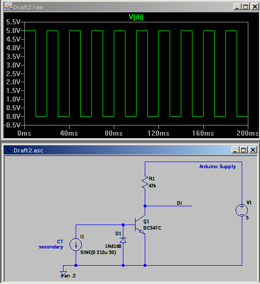
The current transformer (without a burden) will drive whatever voltage is necessary to get the current it wants in the secondary circuit, in your case 150 μA. At that level of current for a 100 A device, you won’t have any accuracy to speak of, but that doesn’t concern you. I’d then connect that - without a burden resistor - straight into the base of an npn transistor (with another silicon diode in inverse parallel with the base-emitter junction to protect it from reverse voltage) and then use that into a digital input. Almost any small-signal transistor and diode should be fine.
That’s only a simulation, but it looks OK. The digital input (DI) will be high with no current, and pulses at mains frequency when there is current. It might actually be too sensitive, in which case add a burden resistor in parallel with the diode. The value will be a matter of trial and error, start with a high value and reduce the value until you get a solid high input with no current flowing, and good pulses with the normal current.
Thanks a lot Robert, the SCT013 that I had actually had an integrated burder but I desoldered it.
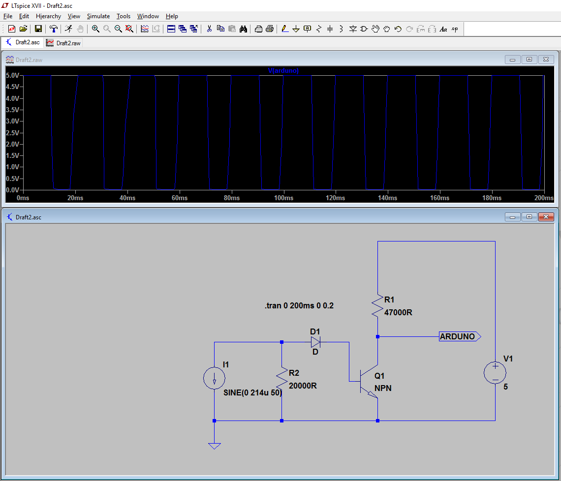
It never occurred to me that you can simulate the circuit!! I went and downloaded LTspice and did replicated your circuit. Also I simulated the way I was doing it with a burder resistor and the diode in series with the CT output.
Could you offer any insight into what differences does your circuit and mine have? As I said I’m a electronic newbie. The simulated output seems to be about the same, but for some reason the output rises and falls a tiny bit more gradually with mine. I wish I had an oscilloscope to see this in the real application.
Your circuit requires 2 diode drops of voltage to turn the transistor on, mine requires only one. Why have a second diode when you already have one in the form of the base-emitter junction of the transistor? (Just make sure it’s adequately rated for the current you’re putting through it.)
If you reduce the CT current sufficiently, mine will get to the same shape as yours, and if you carry on going, the bottom of the ‘square’ wave will round and you’ll eventually get half a sine wave hanging down from 5 V as there’s just enough to turn the transistor on at the peak of the wave.
My D1 clamps the reverse voltage to 1 diode drop. Note, it’s always safe to short-circuit a current transformer. It’s never guaranteed safe to open-circuit one (which is actually what you’re doing on the negative half-cycles, in the absence of R2). That follows from what I wrote above: the CT will generate whatever voltage is necessary to drive the current it needs to in the secondary circuit. A large CT without a burden can easily flash over and destroy itself. The SCT-013-000 has a transient voltage suppressor inside to clamp the voltage at a safe level. That is not necessary when an internal burden is fitted.
A current transformer is the dual of the voltage transformer. So everything you know about voltage transformers, you reverse for current transformers. So a VT generates a constant voltage at a current that varies according to the load, a CT generates a constant current at a voltage that varies according to the burden; a VT is lightly loaded when it is open-circuited, a CT is lightly loaded when it is short-circuited; an overloaded VT burns out because of too much current, an overloaded CT flashes over because of too much voltage; a step-down VT has most turns of thinner wire on the primary, a CT has most turns of thinner wire on the secondary; etc.
If you want to have fun designing your own, I can relate, but there are plenty of current activated relays available in the $20 range that will provide a positive switch at as little as 250ma. Dwyer makes one that retails in that range and triggers at 500ma - 1 A. Just loop three or four turns of the load wire to multiply your 300ma to the minimum trigger current. It even has a little led that indicates it’s on (self powered).
I’ve used many of them in 24Vac control systems when I want to add new controls that need to know the state of another circuit without intermixing the independent 24V supplies in the various HVAC devices. Just google “current relay switches”.
Thanks Robert, very good explanation. I built your circuit and it does work very good! I went with a S8050 transistor since I found an old remote control that had one I could cannibalize. I also put a 100kΩ burden.
overeasy: That’s an awesome tip. I search for some kind of sensor that could do that and never found. I’m guess I didn’t use the right keywords. At this point building my own would be cheaper and faster since I already have all the components. But its very noted for next time I need something like that. Also the tip of looping the primary over the current transformer to multiply the output is something I hadn’t thought about.