Every oscilloscope that I have ever used has a switch, either a physical switch or a software setting, called “coupling” with two settings, “a.c.” or “d.c”. The purpose of the “a.c” setting is to remove any d.c. component in the signal, while the “d.c” setting is to retain the d.c. component. I suspect your PicoScope is set to “a.c. coupled”.
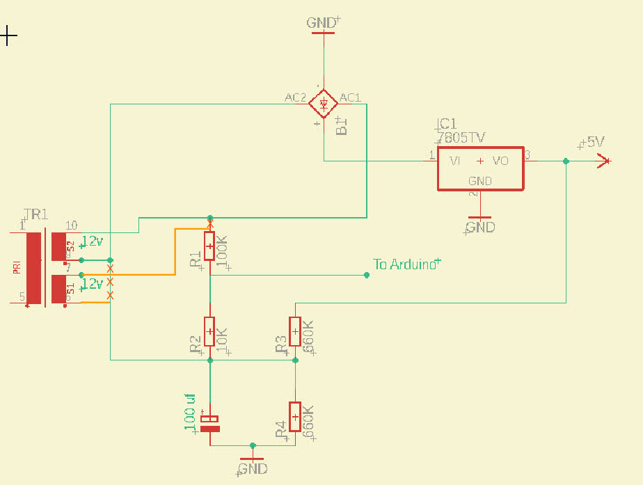
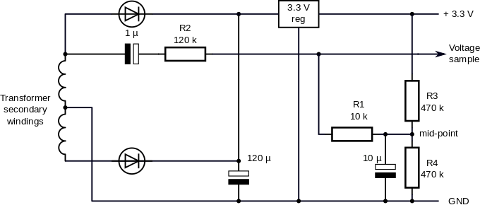
As you have your circuit, you are short-circuiting part of the rectifier through the capacitor and the GND connection. You must use the two separate windings of the transformer. Use one to feed the rectifier and power supply regulator, and the second to measure the voltage.
Also, you do not have a reservoir capacitor to smooth the d.c. input to the regulator. Therefore, your regulator will not work properly.
You are not the first one to make this mistake. From time to time, someone invents a clever circuit that tries to “economise” and only use one transformer, but it is not possible to do it without a centre-tapped winding or an operational amplifier to isolate the voltage you are measuring from the power supply.
I can write a long explanation for you if you need it. If you want to see the problem, think of the bridge rectifier as two switches that alternately connect one end of the transformer winding to the rectifier input and to GND, then think what happens to your measuring circuit.
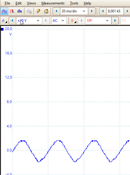
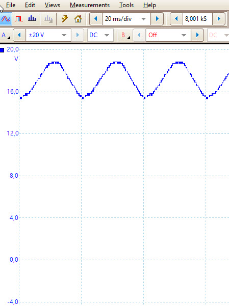
in fig1 you see the AC settings and in fig2 the DC settings.
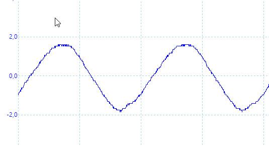
In the DC the offset is about 15.4 V.
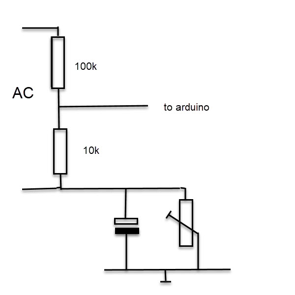
I cannot bring down the offset to 0v. unless i use potentiometer and bring him down to almost 0 ohm. but then he becomes verry hot after a short time. (see fig3).
Yes, but there is a fundamental fault in your circuit. You cannot connect the a.c. and d.c. sides of the bridge rectifier together, which you are doing with the GND connection.
Until you change it to remove the problem, it will not work.
You must do as I wrote earlier: connect the bridge rectifier to one winding of your transformer, and the measuring circuit to the second winding:
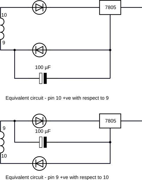
I have drawn the equivalent circuit for what you had - the rectifier is two separate diodes and I omitted the high value resistors. The 100 µF capacitor has a reactance of 31.8 Ω at 50 Hz. You can see that on one half-cycle, the capacitor short-circuits one of the diodes in the bridge rectifier and it is reverse-biased, and on the other half-cycle it short-circuits a diode and the regulator.
Sorry, despite what you say, the drawing is wrong if the transformer has only 3 wires.
You can use that transformer if you use two rectifier diodes in place of the bridge rectifier, in this configuration:
(It works for any voltage, not only 3.3 V)

 .
.