Best hardware option for multiple CTs & WiFi

Cheers Simon, I shall have read later. I bet you can guess where I’m heading with this…

I think a Pi Zero W + STM32 with up to 21 ADC channels would make a superb total solution. full emoncms and IoT server with oodles of very accurate monitoring channels, for not a lot of money.

1 Like

Exactly. I bought some ‘red pills’ as I think they are called last year but haven’t had the chance to really get to grips with them yet. Another option of course is the esp 32 but I could never find a fix on what the ADC on those could do. Maybe time to check that out again.

These things are ridiculously cheap and amazingly powerful - time definitely to move on… (in my case still moving on from starting on an Elliot 903… and some other pretty basic old systems - the processors for the Philips telephone exchanges took the biscuit - if I remember correctly there were 9 instructions and mountains of paper tape).

Roger Clark has done a lot of good work, so well worth digging into what they’ve done.

Simon

Indeed, and to be honest I’m more at home with the Arduino IDE so I could be easily tempted to be lazy and use Arduino rather than get to grips with another environment, However, stm32duino is predominantly aimed at F0 and F1 devices, and to get the number of channels I seek, I needed to look at the F3’s (or so I understood).

Nice one!

That’s actually 21 right?

There’s sorta’ three dimensions to this. It seems complex when you first encounter it but once you start playing with their GUI configurator tool it starts to make sense. The three dimensions are:

  1. number of ADCs (you’ve got 4)
  2. number of channels feeding each ADC (i.e. width of MUX in front of each ADC)
  3. processor pins (you’ve got 64, but not all can be used for analog)

The value for item 2 varies from processor to process, and from ADC controller to ADC controller within the processor, but typically in the 9-15 range. Some of those channels are hardwired to internal signals (Vref, Temperature sensors, OpAmp outputs etc) but most are connected to external pins via a matrix switch.

Assuming you just want to use a single internal op-amp in voltage follower mode (which seems the most popular way of building a low impedance mid-rail) then I think you’d lose 2 pins to that (Vin and Vout). The op-amp Vout is internally connected to one of the ADC’s input channels, so you could sample it for free (i.e. without losing a further pin).

I fired up their configurator tool (STM32CubeMX) set to your board/processor and without trying too hard was able to get 17 analog inputs (a little short of your desired 21):

Analog pins are the scarce resource. You can easily get one more (PA5) by removing the Green LED the development board has connected to that pin. There’s a solder bridge for just that purpose and I removed mine because I too was short of analog pins. Failing that, I think moving to a 144 pin device would have you drowning in analog pins. For kicks, I tried that in their tool and was able to get you 35 channels:

The really good news is that so long as you’re sitting on top of their HAL, it’s quite easy from a f/w point of view to change from one device to another. So you could do all your development on the 64-pin device and move up to the next one if/when you decide you need more channels.

Yes, fortunately the uarts don’t generally conflict with the analog pins, so you’ve lots of pins to support that. In the two examples above I even threw in h/w flow control (so 4 pins in total for you uart). That’s probably a huge overkill for your output stream but you’ve got digital pins to spare.

Yes, I’ve not played with that. I always put a FRAM chip on the SPI bus for that sort of stuff (which is why I enabled a SPI controller in the pinouts above). I didn’t include a /CS for that, but all those unallocated grey pins are available as GPIOs.

It sure is! It’s a lot gruntier than any of the ones I’ve played with. Single cycle floating point divide! You ought to be able to have lots of fun with appliance recognition with that much horsepower.

I did actually mean 18, that should have been “18 ADC’s for 3x Vac and 3x5x CT’s” I was thinking 6 ADC’s per phase not 6 CT’s per phase. So disabling the LED would work well to give me the 18 ADC’s I need. Thanks for working that out.

I had looked at the 144 packaged chips but I thought that was a tad frivolous. I’m thinking a 64pin package might be significantly cheaper and demand less PCB real estate if this was to go to production. Not to mention the headache of trying to populate the first batch of boards by hand, I think I will struggle with 64pins :smile:

It’s far more sophisticated than anything I’ve tried playing with before, so baby steps, first I will aim low and just try to replicate an emonTx type affair using CM and more channels.

I’m sure there’s loads more to discover along the way.

I also noticed the I-NUCLEO-LRWAN1 on my travels, which is also very interesting, although a less powerful device, it has on-board LoRaWAN and it’s ultra low power. Looks a perfect candidate to slap a 3V3 version of the emonTx-shield on for a LoRaWAN emonTx. The current emonTx-shield is only £11 and this device is only £26. Something @glyn.hudson and @TrystanLea might be interested in as they have started dabbling in LoRaWAN.

Sounds like a solid plan. I think that could form a very future-proof basis for further development. Your choice of the M4 is a good one as it includes the DSP instructions. It’ll be interesting to see if the MAC (multiply-and-accumulate) instruction can be of any use when calculating real power. That lets you multiply two numbers together and add the result into an accumulator all in a single cycle. And the SIMD (Single Instruction, Multiple Data) instructions gets used in the CMSIS library to provide very fast FFT implementations. I believe voice recognition and appliance signature recognition is best done in the frequency domain, so that may end up proving very useful for anyone wanting to go down that research route.

Hey Paul (@pb66) no worries at all. I’ve enjoyed the discussion going on here.

I’ve looked into the design of the IoTaWatt and see that its an ESP8266 with dual external ADCs (MCP3208s) which are 12bit and 8 channel.

In my testing it takes the ESP8266 around 150ms to sample it’s A0 pin 1480 times. Assuming the MCP3208 would give similar performance and you had 8 CTs hooked up, doesn’t that mean that each channel has ~1 second gaps between being monitored? (7 * 150 = 1050ms)

Do you just fill in the missing data by keeping track of the sample duration?
Meaning if I measured 100 watts, then wait 1 second, then measure 100 watts again, calculate the watt hours in a way that it assumes the current was a constant level during the 1 second between samples…

Given that disadvantage of having many channels hooked to an ESP (or Uno for that matter) - I assume the STM chips can sample a lot faster than the ESP8266 since they seem to be a lot more powerful. I’ve even read that some have dual ADCs, though I have no idea how to write code in order to take advantage of having two separate hardware channels.

The wiced just came back into stock. I can’t decide if I should just buy it and hope it works out, or order a few MCP3208s instead…

Personally I have no involvement with the IoTaWatt, but yes I believe it is not unlike the discreet sampling emonTx and it calculates the power and energy for the full time line from a partial sample set.

My understanding of how the IotaWatt works (although it may be best to ask Bob Lemaire over at https://community.iotawatt.com/ as Im not 100% sure I have this right) is that it samples one mains cycle from one CT channel then yields to the webserver and service queue before looping back around to make another mains cycle sample from the next CT channel. The loop source code can be found here https://github.com/boblemaire/IoTaWatt/blob/master/Firmware/IotaWatt/Loop.cpp. It manages about 33 cycles per second on @glyn.hudson’s IotaWatt. Which means that on 50Hz and a single configured CT the power measurement covers 33/50 = 66% of the time, with 2 CT’s the 33 cycles/second is divided between 2 CT’s. Each CT’s power measurement is therefore based on 33% of the time. With all 14 CT’s each channel is sampled for 4.7% of the time. That’s still better than the EmonTx discreet sampling which spends 300ms every 10s on each channel or 3%, the samples on the IotaWatt are also spaced out over the full period which will give better results rather than all in one run in the case of the EmonTx. @Robert.Wall is working on continuous sampling code for the EmonTx which covers 100% of the time, which is currently in testing.

Its worth noting that even with discreet sampling covering 2-3% of a 10s period most of the time you get good results see accuracy discussion https://community.openenergymonitor.org/t/meeting-summary-draft/6821. The problem arises when you have fast switching loads such as a triac based solar pv diverter or induction cooker.

1 Like

That’s great info @TrystanLea. Does @Robert.Wall have the continuous sampling code on a github repo somewhere? I’m interested in learning how it works.

It was developed from and closely follows calypso_rae’s energy diverter, which is documented in ‘Learn’.

I don’t intend to release the updated emonLibCM until we are sure that it’s working correctly and accurately. The early version still on GitHub shows serious measurement errors that crept in during its conversion, and should not be used. Although the basic code is the same, there are many changes that were intended to and appear to have improved the accuracy, even in areas where there was no fault, so although that will give you the general idea, it’s probably not worth wasting too much time on it.

Should that not be removed or archived or at least a warning readme added?

Yes, I asked for that to happen when the errors were discovered and I started working to correct them, but it didn’t. There are plenty of warnings on the (old) forum.

Thanks for the info. I’m mostly interested in learning the basic approach of how to address the loop blocking issue. Meaning - how to approach the problem of wanting to sample multiple inputs continuously with an Arduino.

The best I can come up with on my own is to sample each input once per loop instead of sampling one input 1480 times before moving to the next. Its the same number of samples per second, just done in a different order.

I’m curious if there’s another way I’m not thinking of.

So I pulled the trigger and bought that Feather WICED board from Adafruit. I just got a sketch running using emonlib and the board can take 1480 analogRead samples in 11ms.

That’s CRAZY fast compared to the ESP8266 and Uno.

I still have to do some testing with WiFi & MQTT to make sure it doesn’t drop the connection while sampling, which is a big problem I had with the ESP8266.

With this board (and without any fancy programming) I should be able to have 20 CT inputs and measure each of them every 400ms.

The board is a bit pricey, but I wasn’t able to find another turnkey dev board with libraries that also included an STM32 chip and wifi.

I have to say I didn’t have a clue what a “Feather WICED” was so curiosity got the better of me and I took a look

The WICED Feather is based on Cypress (formerly Broadcom) WICED (Wireless Internet Connectivity for Embedded Devices) platform, and is paired up with a powerful STM32F205 ARM Cortex M3 processor running at 120MHz, with support for TLS 1.2 to access sites and web services safely and securely.

this sounded familiar so I looked up a Particle Photon

The board itself uses a Cypress Wi-Fi chip (one that can be found in Nest Protect, LIFX, and Amazon Dash) alongside a powerful STM32 ARM Cortex M3 microcontroller. It’s like the Spark Core. But better.

That too is running a STM32F205 @ 120Mhz, I didn’t look any closer at the specs, but the price is around half that of the feather at $19 verses £35. (but I do not know about the libs available)

We’re just starting to play with some STM32F303’s at the moment which have some really crazy adc speeds as it has 4 physical adcs with up to 22 (or 40) channels (64 or 144 pin packages). at less than a tenner a pop (< £15 for 144pin) you can easily add a esp8266 to keep a webapp seperate to the monitoring FW and still cost you less than either of the Feather or the Photon.

There’s no doubt though, you can get some pretty fast and powerful little mcu’s now for not a lot of money, keep us updated with your progress :slight_smile:

That’s interesting about the photon and the feather comparison - Adafruit sells both. I wonder why they both exist - I’ll have to read up on it some more.

Are there dev boards out there with this chip that are compatible with Arduino IDE?

That was my major draw to the WICED Feather - it works with the Arduino IDE and they have libraries, examples and instructions to get you going (something a hobbyist like myself needs :wink: )

When reading the various STM32 blogs and forum posts etc, there seems to be a very common theme that the Arduino IDE and/or stm32duino only caters for the F0 and F1’s, I think that may of been the case for a long time, but more recently it seems ST are involved with stm32duino and it is now an official ST offering. All those older discussions are not doing the current efforts any favors as I too believed the Arduino IDE wouldn’t do the F3’s but it seems it does.

Once you install the STM core using the boards manager (much like the esp8266 add-on) at the bottom of the boards menu list you see this

image

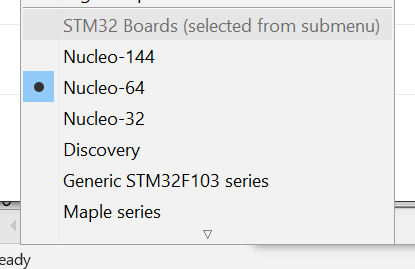
it seems to do each of the Nucleo board ranges (32, 64 and 144 pin mcu’s), the Discovery boards and the more common “F1” or “Maple” (Pills?)

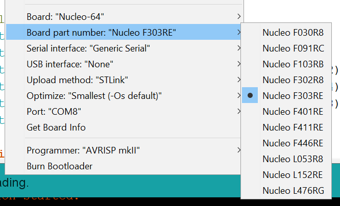
We have Nucleo-64 boards with a F303 fitted but it seems the Arduino caters for most if not all of them. Interesting it does seem to be missing any F2’s, no idea why that might be. I assume the WICED libs are provided by an Adafruit’s boards library or other party?

image

I cannot make any recommendation or vouch for any of this as I’m just starting out on a learning curve myself, but our resident STM guru @dBC has convinced us the way to go is to use the STM32cubeMX utility to configure the HW as there are so many registries and peripherals to play with on these mcu’s, and that gives you a base to add your code to, as yet I have not found this to be Arduino compatible as such (it may be?) but compiling and flashing is as easy as

cd myproject
make
cp build/myproject.bin /dev/ttyACM0

because all the nulceo boards have a on-board/snap-off STlink v2.1 programmer board (STM32F103C8T6 based) that presents itself as a storage device over USB that you you can drag and drop a bin file to (GUI desktop) and it just flashes itself, and for command line you just use cp.

But the ST32cubeMX and drag’n’drop flash leave a bit of a gap between them that is where you write the code, as yet I’m unsure if that can be done in the Arduino IDE or if we can only use a text editor or visual code or atom etc.

For £10 quid for a 72MHz M4 with 4x12 bit adc’s capable of 5msps each or 18msps max overall for up to 22 channels and that includes a genuine (attached) STlink v2.1 programmer/debugger and postage.

https://uk.rs-online.com/web/p/processor-microcontroller-development-kits/8644009/?sra=pmpn

The other “IDE” option is platfomio, which does appear to have extensive libs for the STM range, but I cannot say what it’s like to use, I’ve not had much luck with it in the past, but today I did happen to test it could compile for a f303 on a Pi which it did do without problem. But it isn’t stricktly an IDE like the Arduino IDE is as such, it has plugins to use Atom or MS visual code editors, these you can of course use with the simple “make” option too.

See the STM32 Development for some more reading on the f303 or just the toolchains and utilities etc. I have no doubt there will be a lot more discussions on these.

1 Like

That’s a very interesting development. I’ve not looked at it, but my guess is it would all be about mimic’ing the Arduino API’s such as analogRead() etc. No doubt a whole lot faster than the original AVR analogRead() but still miles away from the performance you can get with continuous sampling and DMA.

That reminds me… I owe that thread an update. I’ve made some progress on the multiple ADC front.

I don’t know quite how “official” it might be, ST probably still consider it a hobby platform. The author of this brief article/flyer dated July last year appears to be an ST employee and I’ve seen his name a fair bit in the stm32duino wiki and forum.

https://community.st.com/community/stm32-community/blog/2017/07/13/stm32-cores-enabled-in-arduino-ide

I also just found this

https://community.st.com/community/share-your-activities/blog/2018/02/21/platformio-stm32-devplatform-v40-offline-builder-for-arm-mbed-stm32cube-arduino

although that is a plug by the developer of Platformio (Ivan Kravets) rather than an ST announcement.

Yeah, me too, things haven’t been going to plan this week but I think I’ve got it cracked now. (famous last words)