Hi, since this week i have my emonTX witk emonESP in use. The setup went rather smoothly. I use a dedicated Raspberry Pi2 and use the bought sd-card in it.
I followed the Tutorial video’s i found on the website which helped me with the configuration.
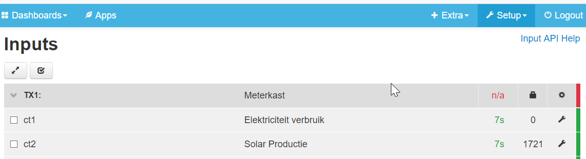
Now my question. Today it is a nice sunny winter day here in Holland and i get these results:
What i don’t understand is why on this sunny day, and use hardly use any electricity, i get these negative readings. (Watch the last positive peaks are from my oven which i switched on for a Lasagna.
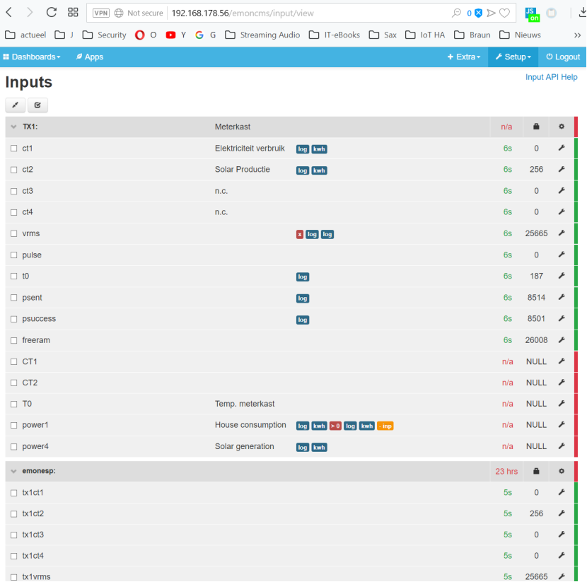
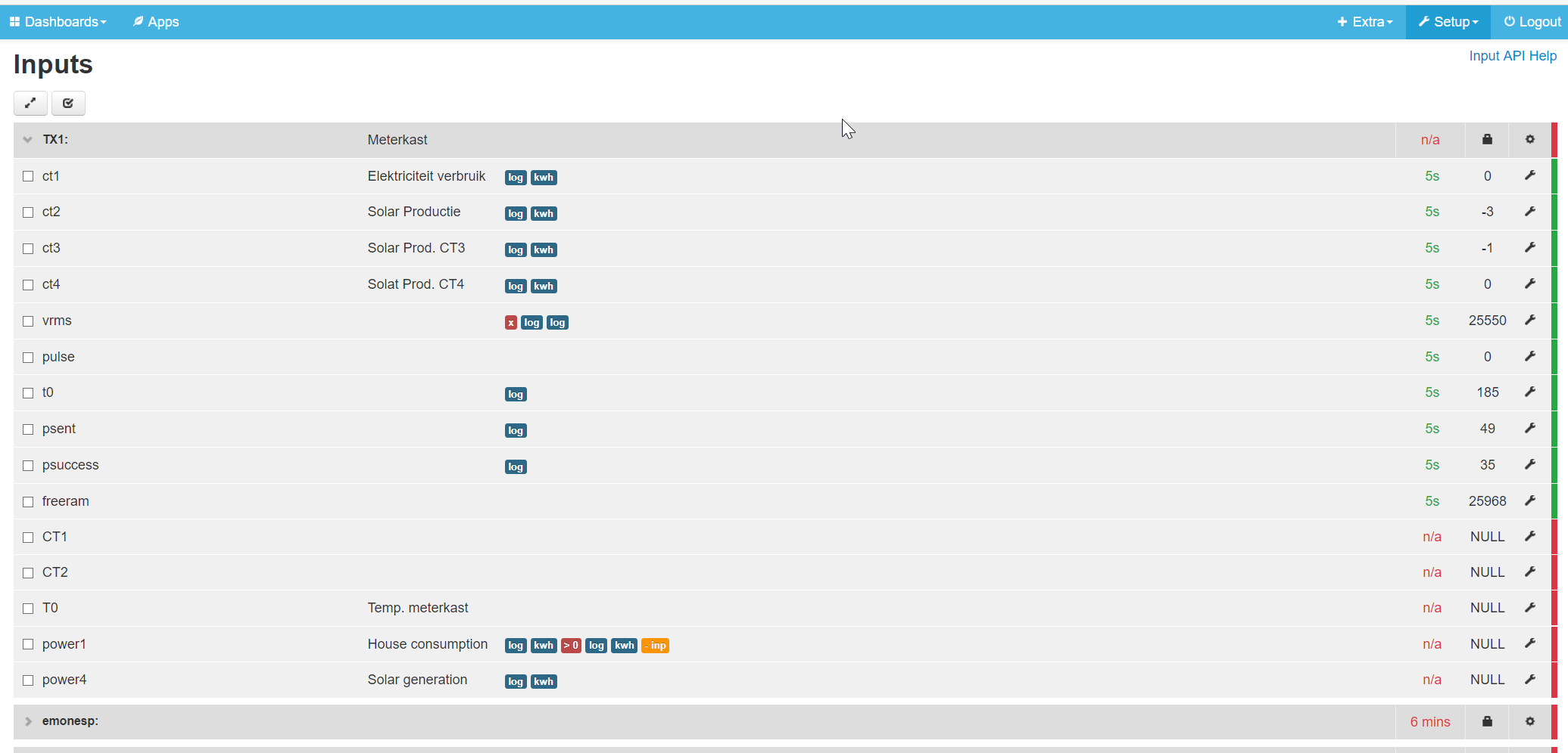
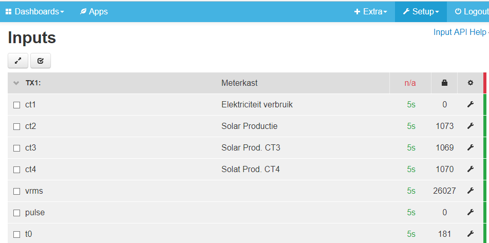
An other concern ragards the Inputs page. I don’t see readings coming in there for mu house usage in W. How can i explain this while the graphs are giving power usage?! Confused!
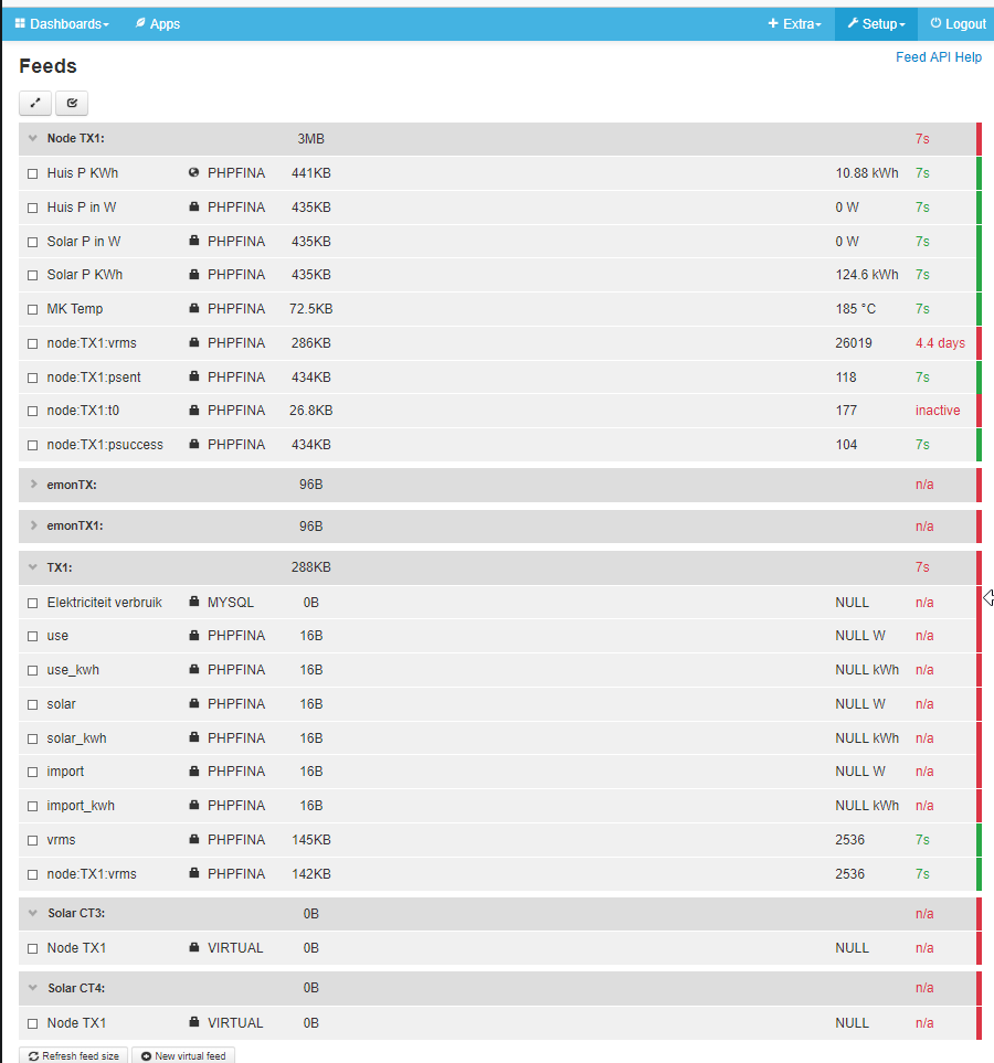
Jet another question. I have a temperature sensor connected on the emonTX (also from the shop) But in the feeds page i see for t0 = 187. That’s a strange reading. The sensor is located in next to the emonTX in the utility closet.
What am i doing wrong with the temperature configuration.
BTW, I use the emonTX with the emonESP and use both a 5V Power adapter (my own) and the 9V adapter (shop) for the mains monitoring, and i put both adapters simultaneously in the mains. (i did remove JP2 on the board)
Further i find lots of information and tutorials for emonPi and emonBasic, but hardly for emonTX or the combination of emonTX with emonESP. For example; I had t find out by lots of searching that in my configuration the emonHUB has no function (because of not using the RF interface).
Also the labels of inputs are different
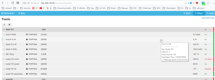
An other question. I have done some testing and different configurations. Is there a way i can reset emoncms to the beginning situation and start again? I guess i can burn a net image on the sd-card and start al over again, but is there a way to get rid of non used Feeds, which i had deleted from the Inputs page, but still are being seen on the Feeds page.
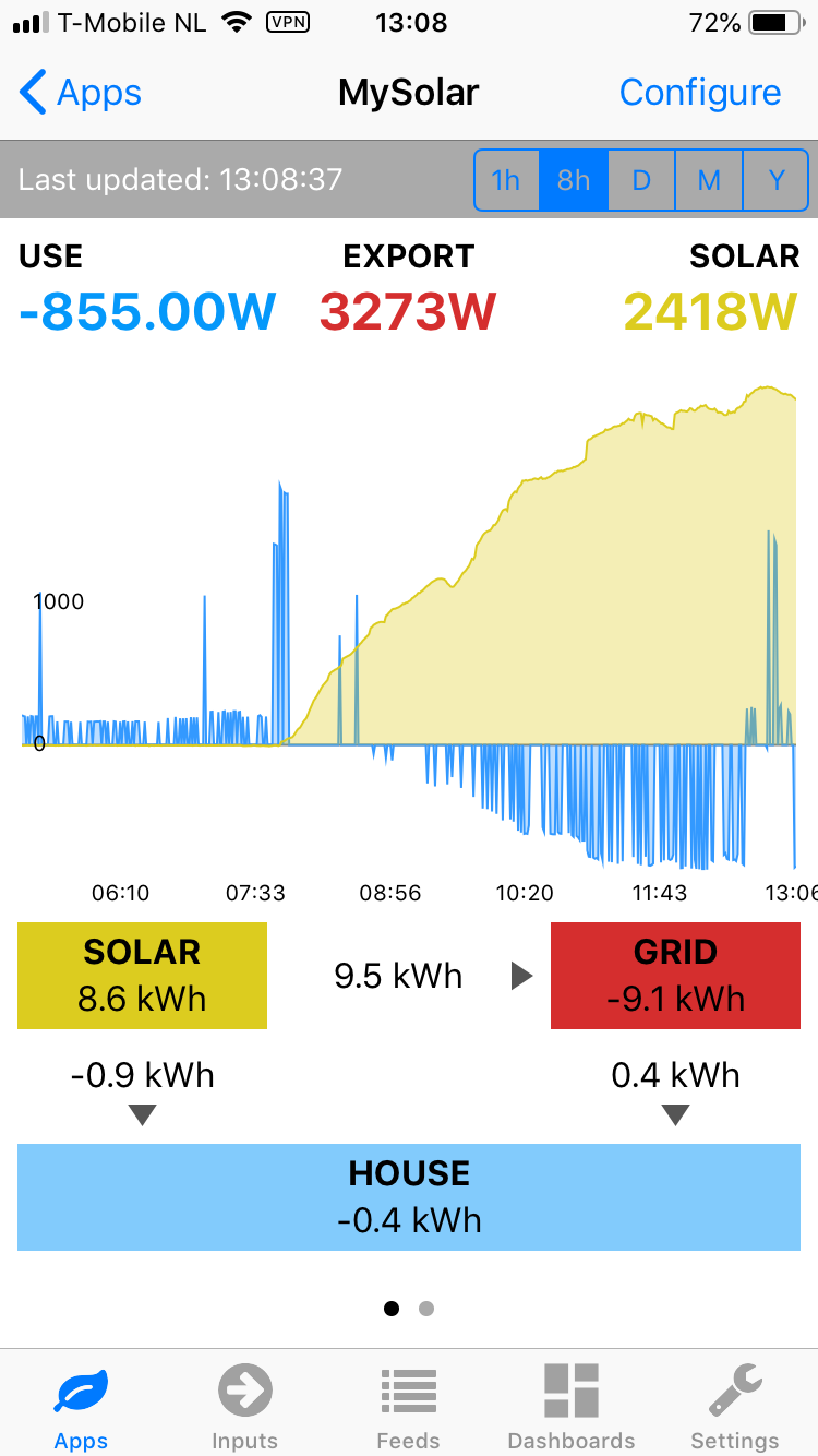
Where the blue line goes below the axis indicates that you are exporting energy back into the electricity grid. I think your current transformer is measuring the current at the grid connection, “upstream” of the point where your PV connects.
That is 18,7°C. We only send integer numbers, so multiply by 10 to send the number. You must add a process on the input page to divide by 10 before you send the value to the Feed.
I cannot tell you how to “empty” emonCMS - @borpin - can you help?
@Robert.Wall
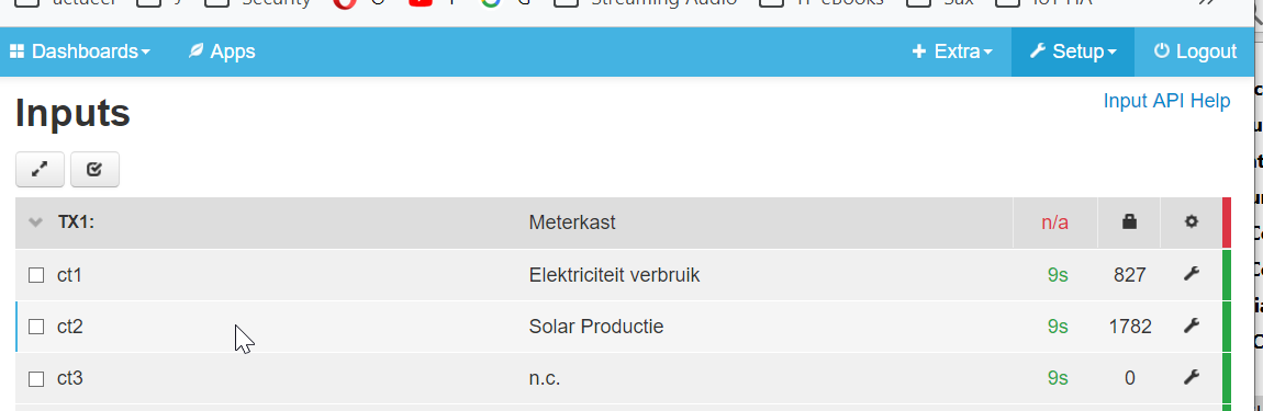
Thank you for your explanation. That makes sense; but then I think the amount of energy delivered back to the grid seems much lower that that received from the solar system… ? At the moment my solar is generating 2335 W, but at the same moment the energy flowing to the grid is 827W. And i am hardly consuming any energy now, no large consumers just the daily background energy usage, about a few hundred W. What do you think about it?
BTW. In my opinion the configuration of my current sensors is according to TYPE 2 as described in the Guide.
As what the temperature readings at the Inputs concerns, yes that was a rather dumb question; I should have figured this out myself. I already adjusted the vrms value with a multiplier factor in that Feed…
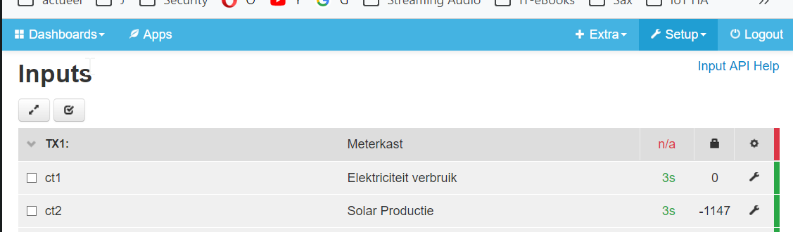
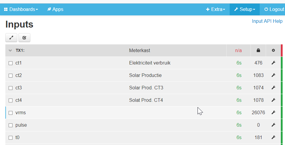
One other question still… In the Inputs I only sometimes see a value by ct1 (so just -856), but most of the time there is only the value 0.
Is there an explanation for?
I must say I like the system! I still need to figure out a lot, and will try to integrate in my openHAB system. It has a great WAF factor; during my testing, my wife was constantly following the energy from the solar and using it for washing- or dish-washing machine. So far its a good investment.
EDIT:
I still have a question about solar generation, energy consumption and delivery to grid.
See this image from the app:
I don’t know how to interpret this. I think this is wrong. It looks as if I export more energy to the gris as the generated Solar energy. And then the next picture taken a few minutes later (when i switched on the electric kitchen over):
Can you confirm your set-up is you have an emonTx with an ESP8266, which is sending the data via your LAN to a Raspberry Pi (the emonBase) running emonCMS.
CT1 = Grid connection, CT2 = PV Infeed.
I think, for a quick check, you should put both c.t’s on the same cable. If they both read the same, then it’s likely that both are correct. If not, you have a big calibration problem with the emonTx - or a faulty emonTx or c.t.
Do you have a programmer? If you have, check that the emonTx is sending valid readings every 10 s. Does the time still update when it shows ‘0’? It appears to do so from your screenshot. If it does, it means that it had received the value zero, and not no value at all.
Hi Robert, First, thank you for helping me with this.
I have received about a week ago an emonTXv3, with the 'ESP8266 WiFi Adapter for EmonTx ’ also called emonESP, together with 4 CT’s, the sd-card with emoncms and the 9V PSU for mains monitoring.
So I do not have the emonBase, but my RPi with the emoncms sw should be the same…
This is how I proceeded.
Before I installed everything I removed the JP-2 jumper. I plugged the CT’s in the emonTX (still no power added) and next put the CT’s on the power leads. Then I booted my own Raspberry Pi with the bought sd-card an opened the emoncms page in a browser.
Then I connected both leads from the power adapters (my own 5V and the bought 9V) in the emonTX and after that I simultaneously plugged the power adapters in the mains sockets.
For the configuration in emoncms I followed video’s from TrystanLea. Unfortunately there are no video’s or dedicated instructions foe using an emonTX…
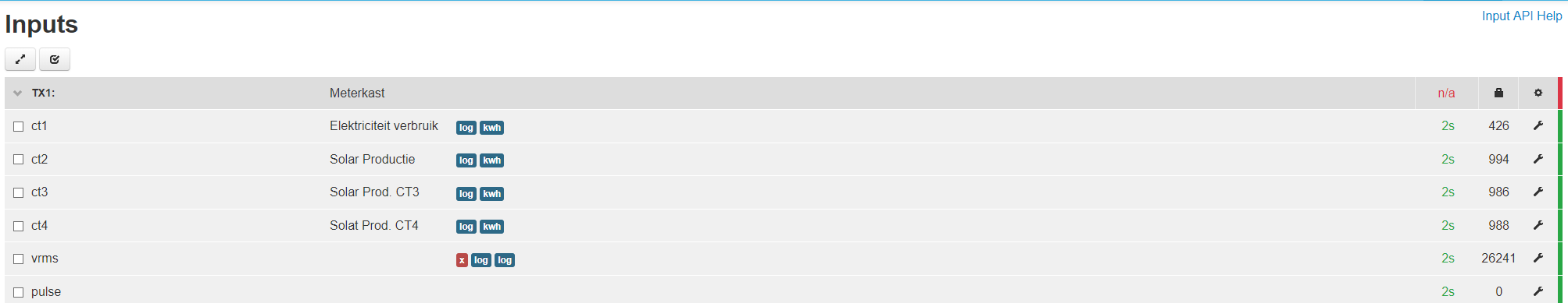
Check with both CT’s on the same power line. First both are here on the Solar connection:
I can test with emonTX ct connections 2 and 3, I can also test with the two other CT’s i have.
(bought because we are planning a second solar system in the near future.)
About a programmer; I do own a FTDI1232 which i use for ESP8266 devices in my HA (like Sonoff’s), if that’s what you mean. I have to see how i can set this up. Perhaps it is better to remove the emonTX out of the utility closet…
I don’t know whether that programmer is compatible, I do know some are not (they might be good for monitoring, but the emonTx cannot be programmed with them).
520 & 1192 on the same cable at the same time? There is surely something wrong there. Are all 4 c.t’s the standard one from our shop)?
If they are, please try with the unused c.t’s and with inputs CT3 & CT4. CT4 is a high sensitivity input - 18 A maximum instead of 100 A, but the calibration inside the emonTx should be correct, and it should be OK on the PV infeed.
I suggest you keep CT1 the same as it is, and try putting the two unused c.t’s to inputs CT3 & CT4 (you need to restart the emonTx after plugging them in) and post some readings. That should show which of c.t. no.1 & Input CT1 or c.t. no.2 & Input CT2 is right or wrong.
(Hint: Once the emonTx knows it has 4 c.t’s connected, you can swap them around without restarting each time - but if there is a big current flowing, unclip the c.t from the cable before unplugging it, and plug it in before putting it back on the cable. It only checks which c.t’s are plugged in when it starts up.)
@deltabert, it depends on what you mean by ‘empty’. If you mean remove all data for specific feeds, I think you can do that from the feeds but I’ll need to check - it might be the beta features only.
To prepare for a test tomorrow, I put all 4 CT’s on the wire from my solar system. So when the sun comes up tomorrow, they should all 4 give the same figures. I switched the emonTX off (both power adapters), put the connector of the CT’s in the emonTX and then I put the clips over the Solar wire (perhaps not really necessary, because there is no sunshine now)
As you can see, in the Feed config I put the processes ‘Log to Feed’ and ‘Power to KWh’ and no calibration on the new CT’s, the same as the other two.
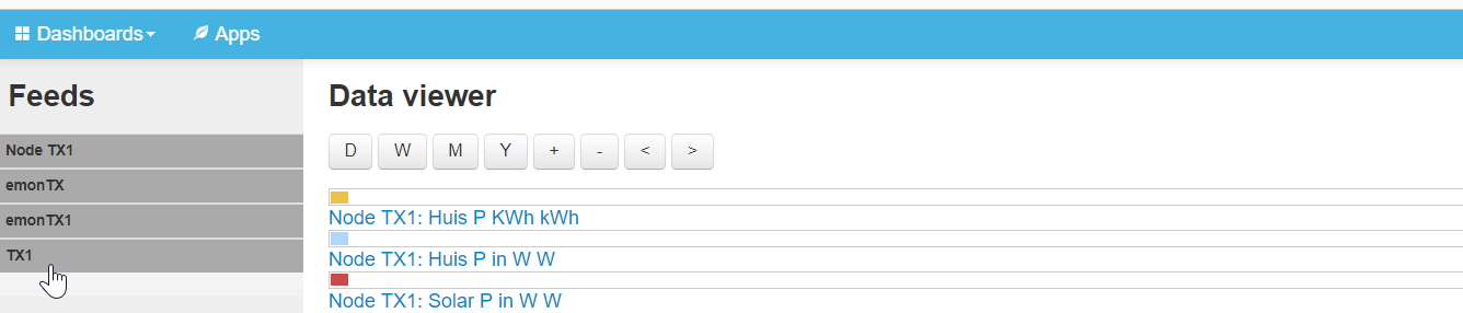
What i don’t know is how to get these 3th and 4th CT’s in the Feeds config under the same Feeds Node TX1 where also the feeds from CT1 and CT2 reside.
The system does not recognize the new CT’s automatically.
So I tried to create two new Virtual Feeds for these CT’s. See:
@borpin Thank you for your reaction. I did the following. For the Feed node i witch to delete, I deleted each individual feed. And after the last one the Feed node was also deleted.
I found also how to move the Feeds from one Feed node to another.
Perhaps I do not have to restart with a clean emoncms after all.
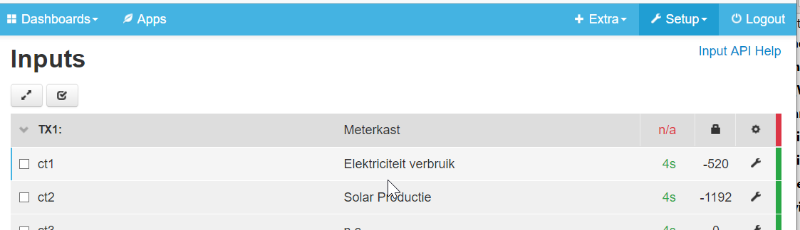
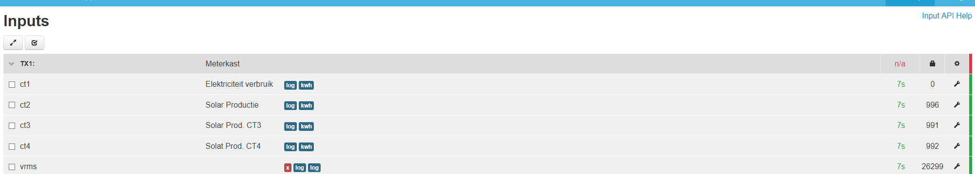
As you can see the readings from CT1 are rather intermittend, but never the same, ore close to the readings from the other tree CT’s.
One moment there is a reading on CT1 for about 5 sec. the next moment it reads 0. Then it takes a considerable amount of time, about 30 sec. before a reading comes up again…
Two other readings, perhaps better to see:
Later, i will switch the CT’s, eg CT4 with CT1, te see if thats changes anything. But i can tell you already that i tried this before, and then it did not change the behaviour of CT1…
I’l keep monitoring today.
Btw, the reason I chose the lead from the Solar system is that this lead has the most slack to put the four CT’s on (but any source would be good as long as all four are in the same lead.)
Btw 2, all components including the 4 CT’s came from the shop and arrived a week ago. The only component not from the shop is the 5V adapter, (which is my own and supports 2A) and the Raspberry Pi2, from which i had already a couple in house. Also emoncms sd-card is from the shop.
The reason i chose for the emonTx is that we are planning a second solar system at the house.
At forehand i have had contact about this with @glyn.hudson, also about the combination of emoncms and openHAB. This combination on the same RPi i tested before ordering.
You would expect a small amount of variation in the numbers, just how the calculation is done) but there certainly looks to be an issue with the CT1 input and if you have swapped the CT itself, it does indicate an issue with the EmonTX. @Gwil and email the shop might be a good place to ask.
Hi @glyn.hudson, Yesterday I have send you an answer on the test about swapping CT’s in order to determine if the problem is a faulty CT or the emonTx itself.
I did this test and reported about this via e-mail to you. Could you please get in touch in order to arrange a replacement?
Hi Robert,
Sorry, I should have let you know the results also right away. Unfortunately it is the input for CT1 on the emonTx. I exchanged CT1 with the other tree CT’s but the problem remains on CT1.
Thank you very much for your help so far.
@Gwil, Thank you for your reply. I just read the email you send and I have reacted on that…
You mention that you will tomorrow send a CT together with the other components I asked for.
But in my and @glyn.hudson opinion, it is not the CT, but the emonTx V3, which has a problem at the port for the ct1. (Please re-read the forum messages and my e-mail…)
Hopefully you are not sending the wrong component…