Before The Begining 2025

Hello Community, this is my first post. Please be patient with a learner!
What setup for my system? I will learn as I go.
It’s an all-electric passive house with PV, Battery, Heat Pump, EV Charger, Diverter to HW. A rough schematic is attached. My first requirement is displaying energy flow information in the kitchen. After that, control of the battery and import/export. Equipment is SolarEdge, Fronius, BYD, MyEnergy (Zappi+Eddie). The house was single phase but I introduced three phase which feeds the Zappi, battery, Fronius, and provides a single phase supply to the house. I use 20k kWh/annum including self-generation and import.

Schematic 2025.xlsx (11.9 KB)

Well… that is a lot of kit!
A simple answer is difficult as it would surely over-simplify, so this is more of a tactical response, along the lines of “how would I analyse this” if I had just moved into your house. Also, the answer very much depends on your starting point in terms of physics, electronics, and computing… and how happy you are doing what most people get an electrician for…

First thing is to do your homework concerning what the kit is already doing in terms of power etc, and what data can be acquired. Quite a lot of inverters have an RS485/Modbus interface which can give access to useful data. A simple dongle plugged into an EmonPi can translate that into a form which the EmonPi can record for you to analyse with EmonCMS.

EmonPi is a good bit of kit to get, to get working, and to learn with. The usual approach (which I started with) is to use “current transformers” (aka CT) but I now also have a SDM120 (there is a 3 phase version) for my heat pump consumption. It is a module as fits in consumer units so if you have a spare slot, or an existing “dumb” energy meter module, that is an easy replace.

Draw a diagram, working out what the flows of electricity are, and where you need to measure.

Depending on your heat pump, you may be able to get “good enough” data on heat output without needing to fit the OEM HP monitor kit. For example, I have a Daikin EDLA and use the ESPAltherma. I calculate an estimate of heat output based on flow rate and temp increase and get CoP values which are generally close to the data book values for the EDLA.

Take your time in putting monitoring in place; having planned ahead, take one bite as a learning experience. For example, an EmonPi with 2 CT;s. Get happy with that then put an SDM120/360 in with an RS485 dongle on the EmonPi. Direct query of inverters by RS485 is a bit more hairy… However, it you look into the Home Automation system, maybe that will be more accessible. Lots of people have written adapters.

I’ve been singularly unimpressed by most products in terms of access to data. Each manufacturer has their own app and clound-based system but generally with little scope for integration.

hth a bit…
1 Like

:+1:
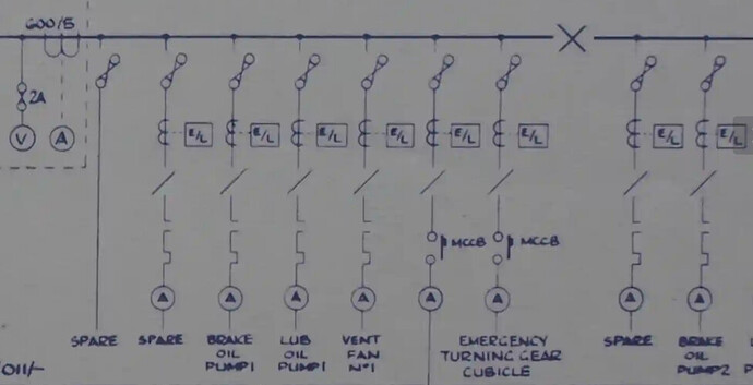
I strongly second that - I looked at your “schematic” expecting what we call a “single line diagram of connections”. If you’re not familiar with the idea, this will use a single line to show the power flow (i.e. ignore neutrals and earths), but do have 3 lines where you have the 3 phases, include meters, consumer units, with their switches and circuit breakers/fuses (with their ratings) and of course all the sources and sinks of power.
This might give you some idea of what one looks like (part of an industrial switchboard - the main supply is off the picture on the left hand side, there is a backup supply feeding in from the right-hand side):

To add to what Adam has written, bear in mind that both emonTx5 and emonPi2 can do 12 channels and 3 phases - and feel free to bounce your proposals off us before you order.

One maybe not obvious point is, are your three-phase loads ‘balanced’, i.e. is it always the same load on each phase. If it is, you don’t need to measure all three phases, measure one and multiply by three. And arising from this - if you’re prepared to make some small modifications to the software, you can allocate any current channel to any phase voltage, which gives you enormous flexibility. (And if you don’t fancy that, if you ask nicely, The Shop might do that for you.)

And I’d finally add one more caution - DO NOT try to learn too much too quickly. There is a huge amount of information in the Docs section, many times more buried in the forum and yet more in the brains of the contributors here. Don’t be afraid to ask, the only silly question is the one that assumes we know what you’re thinking about.

Thanks Robert and Thanks Adam.
I’ll start with the single line diagram of connections, and then consider next step, be it emonPi2 or emonTx5.
I’ll be back soon with the diagram.

Bear in mind it’s not ‘or’ - the emonTx5 is not a stand-alone device, it needs either an emonPi2 or an emonBase to do something with the data it sends out.

Therefore, if you follow Adam’s advice and start small, it’s almost certainly (depending on Ethernet/Wi-Fi LAN coverage) an emonPi2 + emonVs (possibly 3-phase) monitoring the supply into and out of your 3-phase c.u.

Great, thanks. Can you suggest a simple program to draw a digital schematic of connections?

For all the diagrams in ‘Docs’ that I’ve drawn, I’ve used Inkscape. But you need to create your own symbols. It’s a bit of a bind the first time, but once done, you just re-use them. I’ve not researched any other applications, many don’t use the British symbols anyway and if that’s the case, you’re faced with drawing your own again.